Friday, 14 October 2011

Sentinel Loco Boiler Replacement - Big Time!

Friday 14th October 2011 was a beautiful, sunny, autumn day, ideal for picking up, transporting and reinstalling Sentinel 7109's big 200hp loco boiler.

Starting out at Mendip Steam Restorations Ltd, Paul (star of the day) of R J King first puts the boiler on the lorry. (Also on YouTube).

About here:
On the back of a lorry (from where it must not fall off)
Then out on the road:
Stoke St Michael's motorway
Through Stretton on the Fosse:
No boilers coming the other way
Then, crossing the road to Chilcompton, signs of the visible bit:
Summit to think about!
Finally arriving at Midsomer Norton Station for repatriation:
Not seen each other for a while!
Attach the chains for the lift...
...put it over here...
...through that hole in the cab roof...
...down a bit...
...to here
This is how it's really done: (Also on YouTube).

Followed by this: (Also on YouTube).
Finally 7109 ends up back on the level, parallel to the ground, for the first time in years.
Back on the level
I think this is classed as a project milestone!

Thursday, 13 October 2011

Why you need a Pointy Hat

As delivered, this elegant, Penberthy, displacement lubricator will flood the cab-mounted Worthington Simpson Boiler Feed Pump's (WS BFP's) steam chest every time it's topped up. Not good!
Looks good but hides a flaw
Let's see why.
Mounted on top of the WS BFP's Steam chest
The lubricator relies on being mounted vertically with steam oil filled to the top of a centrally located, internal tube.
Main pot removed to show the internal tube
In operation, some steam from the steam chest below is pushed up into the air gap at the top of the main pot where it condenses into water.

Being heavier than oil, the water sinks to the bottom and raises the level of the oil. The oil then spills over into the internal tube and back down into the steam chest below. So this is how the steam oil gets into the steam chest at the same pressure as the steam.

How does the oil get into the main pot? Well, you take off the filler cap and pour it in or so you expect until you actually have a look inside.

The top of the tube is open!
The tube has nothing to prevent oil being poured straight down it into the steam chest. Whilst this probably would not do any great damage, the steam chest would certainly get more oil than required!

I've concluded that there must be a missing part which blocks the hole but still allows the oil to spill over into the tube as intended.


I spent a lot of time figuring out how this part could block yet not block the tube top. Eventually I came up with a sort of castellated pointy hat thing!

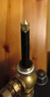
Castellated, pointy, hat thing drilled from below to meet six holes and...
...which can sit on top of the tube like this
Now when you look in the top of the pot, it's like this:
Pointy hat top
So pouring oil into the filler will now put it into the pot and not straight into the steam chest!

I wonder if it will still work and what was there originally?

Saturday, 8 October 2011

Many thanks ...

... to all who kindly made donations to the Sentinel 7109 restoration project at the S&DRHT AGM on Saturday 8th October 2011. Much appreciated!
The queen definitely looks younger in this photo!

Thursday, 6 October 2011

Boiler Lagged and Cladded

Nigel Dickinson, Mike Colborne and myself spent Wednesday 5th October 2011 at Mendip Steam Restorations' workshop affixing Sentinel 7109's boiler lagging and outer cladding sheets. Previous articles (1, 2) have shown the preparation of the 'duvet' and outer cladding sheets ready for this day.

First of all, the boiler had to be brought inside from where it had lain for some months.

Tight manoeuvres in the yard...
...and a squeeze past obstacles in the doorway
Once set up inside, the two happy-chappies got to work with the lower 'duvet'...
Nigel and Mike clearly enjoying their work!
... followed by the upper 'duvet'.
Self-adhesive Aluminium tape fills the gaps...
... to hold it all together
The apertures in the finished 'duvet', thankfully, really did fit over the fittings as planned.

Snug fit
Then the cladding sheets needed to be fitted and pop-riveted together to hold them in place. The sheets also had to be riveted to a lower ring support on the boiler and an upper ring above. Whilst the 'duvet' had gone on easily, this was a more onerous task requiring the sheets to be attached and then squeezed over the 'duvet'.
Upper ring holes being drilled-out ready to take the rivets
Nigel clearly considering how to drill his left thumb joint!
Things got rather busy and strained in this process so the photographer had to take time out to do some real work!

So we got it done in a day! I have to admit to going home feeling rather smug and relieved that it was ready to install after really quite a long time in preparation.
The finished, painted article ready for installation in 7109
A date is now set for the boiler to be craned into 7109 and it's soon (but secret!).


Spending a day in Mendip Steam Restorations' workshop was an experience in itself. This is a place where real heavy-duty work takes place; I was immensely impressed at the scale of the activities and how things progressed quickly compared to the months we have taken on 7109's activities.

Here's a few photos to illustrate.
Andy Melrose clearly ready to attack the boiler to the right!
(Note the 100HP Sentinel fireboxes in the background)
Fitting the boiler front section with its owner close to hand
This is probably the biggest lathe I've seen. I don't know what the component was but it was about 5 feet in diameter.
Richard Philips (not posing) whilst doing a 'little' turning
(he was actually shoeing the pet dog away!)

Large-scale turning in action (also on YouTube)
Traction-engine boiler currently under construction (1)
Traction-engine boiler currently under construction (2)
Many thanks to MSR for all the help and advice over the months - keep up the good work!

Tuesday, 4 October 2011

Chuff-Synchronisation - Now what's that all about?

Richard Nixon, drawings' custodian of the Sentinel Drivers' Club and Isebrook's carer, emailed me recently with a technical query about double-engined Sentinels.

His concern was that, with two engines, if they were not coupled together so that each chuffed up their respective chimneys at the same time, instead of air being drawn up through the fire, would each engine merely suck air back down the other engine's chimney?

To understand the point, a bit more needs to be known about how a double engined loco works. In particular, each engine has its own double chimney mounted immediately above the firebox.

Twin double chimneys
Plan view of boiler showing the twin double chimneys
Single exhaust pipe divides to feed two chimneys
Blasting exhaust steam through a nozzle in each chimney tube draws air upwards through the chimney. The air should be drawn up from below through the firegrate.

This all works fine if both engines chuff at the same time; however, if they don't then air can be drawn down the un-chuffed chimney instead of up through the fire (probably being the path of least resistance). The result would be a poorer fire in times of need.

So are 7109's two engines chuff-synchronised?

I had originally thought this was true and that the two engines on 7109 were gear locked together.

A gear case on the end of each engine crankshaft
with the larger gear case below
From the above picture, it looks as if there would be a gear for each engine in its upper gear case (black, like a pair of eyebrows) meshed with the larger gear in the rusty/grey gear case below. (There is the same situation on the other side). If all these gears were in place as described, then the two engines could have been chuff-synchronised together.

However; to my surprise, when I first undid the oil filler cap in the front engine's off side gear case (the one to the right in the photo), I found that the gear case was empty. On the near side, the rear engine's case was also empty.

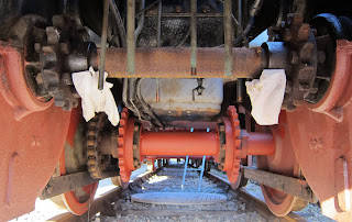
At first, I thought we'd been diddled but then it dawned on me. There is a sprocket for a chain to drive the front axle from each lower gear; the two gears are not linked and rotate on a fixed, 'dead' axle. Thus the engines rely on the chains being set appropriately and tightly enough to achieve chuff-synchronisation.

Twin sprockets for chain drive to front axle
It's doubtful that chuff-synchronisation was achieved particularly well in both directions due to slack in the chains.

This situation evolved in later double geared locos such as Sentinel 9622.

Sentinel 9622's drive chains
9622's chains are double width, presumably for extra strength. These were most likely adopted because of the double gearing. Depending on whether low or high gear is selected, the drive will be transferred to the front axle by one chain or the other but not both. Hence all the driving force has to go via a single chain in contrast to 7109 where both are used at the same time.

To make the double gearing work, both engines are locked together at the end of the crankshaft where the gear is engaged. This happens by having a gear in each upper casing meshed with the gear in the lower casing.

However, there is still more to the picture: double geared engines have a neutral setting in which neither high nor low gear is engaged and the engines can be run with neither load nor locking together. This enables better warming through of the cylinders prior to loco movement.

Front view showing different sized gears at each side
(Diagram derived from 1930 A2 drawing, courtesy Richard Nixon)
Side view of upper and lower gear casings
(Diagram derived from 1930 A2 drawing, courtesy Richard Nixon)
Of course, the asynchronous rotation of the two engines in neutral means that when they are put into gear, they could be in any relative state of rotation. As such, sometimes they might be chuff synchronised and sometimes not in an unpredictable manner.

So Sentinel 7109, 9622 and other double engined locos have the same problem.

There is yet another consideration and that is to do with the resonant frequency of the chimney system. This may not be relevant if the chuffing frequency never gets high enough to reach resonance and I am sticking my neck out here due to lack of in-depth knowledge of this type of system. (Ask a designer of resonant, high-performance, car exhaust systems!).


Below resonance, a chuff up one pair of chimneys could easily pull air down the other pair if out of sync. At resonance, I do not know what happens. Above resonance, the chuffing will be so fast that sucking air back in won't take place and each chimney will behave as if sealed. (I'm assuming that the chimney system behaves like a ported loudspeaker enclosure).

So the conclusion to all this? I think we'd better just try it and hope for the best!
Related Posts Plugin for WordPress, Blogger...