Showing posts with label Valves. Show all posts

Saturday, 23 February 2019

Frost Damage February 2019.

Sentinel 7109 was surprised by a sudden frost in early February 2019 and suffered some damage to the pipework feeding the cab's boiler feed pump.

In June 2013, I wrote extensively about the construction of an elaborate plug valve with a hidden secret. It was originally fitted in 1928 so was a historical gem.
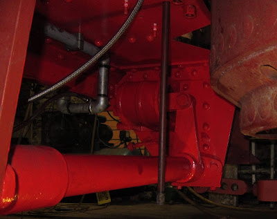
Plug valve in water feed line.
However, after the frost, I found it looking rather sorry for itself.
Split top bit
On taking it apart, I realised that it was beyond repair as the internal plug itself had split into two pieces.
Split plug
It's a shame to lose an original part in this way but it was also an opportunity. I suspect the 1928 construction had perhaps been done in a hurry; Joyce was a prototype after all. Where the pipe came from the tank to the 'T' piece, a strainer was hidden across the top of the 'T'. The valve was downstream of the strainer.
There was a disadvantage with this in that to clear the strainer by removing the plug from the end of the 'T', the tank had to be emptied to avoid a personal irrigation. So the valve should have been upstream of the strainer!

I've resorted to modern parts to rebuild the valve and strainer with the disadvantage removed.
Ball valve and 'Y' strainer
The pressure on the ball valve is only the head of the water in the tank, about 6 feet max., so there are minimal requirements for it. The 'Y' strainer is now downstream of the valve and the strainer's cap (pointing downwards) can also be used to drain the water pipe for frost precautions as well as cleaning the strainer. With any luck, the new strainer will be less restrictive than the old one so the water pump should be more efficient.

I'll tidy up the appearance in due course [as below].
With a lick of paint...
...And some frost protection where the pipe can't be drained

Friday, 8 January 2016

Boiler Fittings (8)

Thursday 7th January 2016 saw Sentinel 7109's original boiler water gauge glasses being fitted finally as in the photo below.
Right hand gauge glasses
I last wrote about these in April 2013 when I'd obtained replacement glass protectors and checked that they would fit. Now the valves are in for good (hopefully).
Gauge Glass Valve arrangement similar to 7109's
Having remembered to insert the new 3/4" stainless steel balls into the lower valves to reduce the amount of steam escaping should the glass tube break, I proceeded to attach the component parts to the boiler. The upright steel tube is very straight and is used to ensure that top and bottom valves are aligned accurately when the glass tube is tightened in place.
Steel tube passing down through the upper valve to the lower one
It was not that difficult to achieve the alignment which is probably down to the 

curved surface of the valve faces matching the curvature of the boiler. I'm glad that new valves with flat faces did not have to be used!
Upper valve
Not so obvious from these photos is that each valve face is sealed to the boiler using a combination of graphite gasket with suitable lashings of Rocol Steamseal.
Lower valve showing close fit around the steel tube
I was then able to put the glass tubes in place and tighten them up. The word 'tighten' here is quite subjective. Sentinel used hexagonal graphite packings for this situation as below.
Hexagonal glass tube packings (photo from Heritage Steam Supplies' website)
They fit around the glass tube and are compressed to seal the tube. However, they should not be overtightened to prevent the glass being destroyed and they should align with the hexagonal spaces within the screw clamping mechanism. One of the glasses did not seal well so I may not have got this right and will have to recheck.

But how did I know that the seal was not so good...? That will have to wait for my next article (and I promise it will be worth the wait!).

Monday, 4 January 2016

Implementing 'A Little Arithmetic'

In a recent Sentinel 7109 article, I did some 'arithmetic' to enable a new boiler blow-down valve to be fitted. The result was this elongated heavy duty hex nipple pipe fitting made by Justin Goold.
Elongated Hex Nipple
The photo below shows that it has provided the solution required and is a good, strong fit to support the substantial high-spec blow-down valve.
The Valve is firmly screwed into the wash-out plug-hole
Another view shows valve handle in its closed position. An extension handle like those used to turn-off your household water supply in the street will be useful here.
The handle is reached from the off-side
preferably with a long reach extension
Down-stream of the valve, the pipe fittings are galvanised malleable iron as there is no longer the boiler pressure to withstand.
Not a good place to be when the valve is opened!
Another hole in the boiler plugged!

Important Note: The boiler has four washout plug holes at 90 degree intervals. For washout purposes, only the three actual plugs should be used. Only under extreme circumstances should this valve and its hex fitting be removed. The result would be that it will not be able to be tight and in the correct orientation after refitting due to wear on the threads when it was tightened up previously. Thus, it has to be a fit once and leave well alone item.

Monday, 21 December 2015

Boiler Feed Plumbing

On the shortest day of December 2015, Sentinel 7109 received another milestone of reassembly.
Twin Check Valve unit with single check valve to the right
The pipework connecting the two engine-mounted water pumps to the boiler's twin check valve was completed. The single check valve used with the cab mounted pump is in the shade to the right. (A check valve allows the water to only flow in one direction. Hence, water can be put into the boiler without it coming straight out again!).

The twin valve takes water from each pump but allows it to be recirculated to the water tank if not needed by operating the red handles. This is important because the engine pumps are always working when the loco is moving.

I'm really pleased with this pipework as it is original but was not fitted when the loco arrived at Midsomer Norton in 2004.

Sunday, 13 December 2015

Steam Brake Air Tested

In June 2012, I last wrote about Sentinel 7109's steam brake cylinder. Time passes and I've learnt that restoration is not a rapid activity!

The brake cylinder was reinstalled on Monday 7th December 2015 and here it is in place bolted to the left hand frame member to the rear of the boiler. (Bearing in mind that I can only just lift the cylinder on my own, getting it into place under here was not a straight forward exercise and required a selection of trolleys, levers, bits of railway sleeper and a lot of ingenuity to get it home!).
Brake Off
Spot the difference!
Brake On
To see it in action, here's another of my little video clips (Also on YouTube).

Sounds like heavy breathing!

The testing involved connecting a compressed air supply to the Driver's Brake Valve (DBV) inlet. Movement in the video was controlled using the DBV itself as would be normal practice with a steam supply.
DBV Top Left
The brakes still need to be adjusted but that can't happen until the front drive chains are in place and the axles located for the correct chain tension.

Checking back over the 'blog, I've not been able to find anything on the Driver's Brake Valve itself. I've had the photos since December 2012 but they slipped through the net.

The Driver's Brake Valve has an operating shaft and three connections to it - the steam supply inlet from the boiler; the outlet to the brake cylinder and a drain to atmosphere to release the pressure on the cylinder piston to let the brake off after application.
DBV connections
DBV Operating shaft
The operating shaft is extended across the rear of the cab to allow the brake to be operated from either side.
Dual Controls 1927 Style!
I took the following photo just after taking co-ownership of 7109 in 2010. A few bits & pieces had been removed and examined ('played with'). There was a long journey ahead!
DBV in October 2010
For completeness, here's the Sentinel factory drawing of the DBV. It is a general drawing showing that it could be operated from either end although 7109 did not use it that way.
Sentinel DBV Sectional Drawing
Other locos mounted the DBV in the centre rear of the boiler with handles either side.
DBV in Sentinel 9599 (William Mk1)

Tuesday, 8 December 2015

Remote Control - 1927 Style in 2015

I began this small series three years ago here. With due regard to health and safety, I did not complete the construction as there would have been a trip wire to negotiate at the same time as squeezing into the right front corner of the cab where most of the vacuum braking and safety valve apparatus was being made resident. (I've lost count of the number of times I've had to breathe in very deeply to avoid impaling myself on the safety valves and vacuum gear).

The trip wire is now in place ready for the unwary (probably me on bad day!). There is a lot more to go in this corner and much not obvious in this photo.
Trip wire in place
Below the cab floor, the cable attaches to the exhaust condensate valve. (Also shown here is the new stainless steel braided (High-tech!) mechanical lubricator feed pipe to the regulator steam supply).
Underneath end of the remote control cable
The cable passes through the cab floor by the vacuum pipe.
Through the cab floor (1)
The two water feed pipes from the engine-mounted boiler feed pumps are showing - and still need to be linked to the boiler. The cable looks as if it will rub against the water pipe. Some care will be needed here.
Through the cab floor (2)
From a different angle:
Through the cab floor (3)
Looking at the photos in the earlier article, it brings home just how much has been done over those three years (and that the amount still to do is looking a lot more encouraging!)...

Wednesday, 25 November 2015

A Little Arithmetic

In one of my previous articles, I showed the boiler having a leg to stand on. I remarked that the 'leg' would be made from red band steel pipe when complete. However, when I considered this further, it would have meant a fairly long section of pipe on the end of which would be the blow-down valve itself.

I concluded that the torque required to operate the valve repeatedly could potentially loosen the pipe where it screwed into the boiler. In the worst case, it could damage the boiler's thread.

I decided that a heavy duty steel nipple would do the job well and be much stronger as well as being shorter. However, when I came to try such a nipple, it went up to the end of its tapered thread in the boiler's hole. Thus, I was not confident it could seal properly.

The Heritage Railway Association (HRA) have published a document on boiler washout plugs. They are very concerned that the male and female threads for boiler plugs should be compatible and not a mixture of seemingly well fitting threads. Whilst this blow down valve is clearly not a boiler plug, it does fit into a boiler plug hole with a tapered thread and I have ensured that the threads will be the correct fit.

Sentinel used 1.25" tapered BSP threads for their boiler plugs although they made the taper longer to allow for wear due to regular removal and replacement. Now for the arithmetic:
Plug + Nipple = Plug-nipple!
I asked Justin Goold to make me a nipple with the boiler plug thread at one end with the normal BSPT at the other.

I have yet to check the fit but I'm sure there will not be a problem initially. I say initially because if wear does take place, the handle of the blow down valve will rotate with each tightening and not so easy to operate. Some care will be required.

Saturday, 21 November 2015

Vacuum Braking (15) Implementation (8)

Working Under Less Pressure than the boiler, the vacuum brake ejector requires 60 psi to work most efficiently. I began to describe this in an earlier article.

The missing item was a gauge to measure the pressure entering the pressure reducing valve.
Ejector Pressure Gauge Mounting
The gauge is clamped to the upward tube and marked mid-way between 40 and 80 psi.

Steam gauges are always fed by a tube with a loop or dip before the gauge. It collects condensation and prevents the steam entering the gauge and melting the soft-soldered delicate parts inside.

Friday, 17 January 2014

Vacuum Braking (5) Design (4)

One difficulty with Sentinels is that the 275 psi boiler pressure is above the 250 psi rating of many off-the-shelf valves. At 275 psi, water boils at 212 DegC so special materials are needed to withstand these conditions. Any valve that has to isolate a steam supply from a boiler has to be rated as such.

Three new ones are required on Sentinel 7109:

  1. A 1/2 inch type to isolate the vacuum braking supply.
  2. A 1/2 inch type to isolate the supply for a steam cleaning lance.
  3. A 1.25 inch type for the boiler's blow-down valve. (See later).
They were made in Switzerland by Valtaco and sourced from Poynton Valves. This is what they look like:
The 1.25 inch and two 1/2 inch ball valves
These are known as ball valves because the moving part of the valve is ball-shaped (but with a hole through). To begin with, investigation had sent me towards using gate valves as these are intended for isolating supplies rather than regulating a flow. However, gate valves are better suited to liquids at relatively low pressures. Ball valves can be built to be much stronger and are very effective at isolation duties.
Full bore when open
Those of you who have followed my blog for some time will recall that a blow-down valve had been obtained some time ago; however, my wariness about fitness for purpose of high temperature and pressure components has been heightened as the project has progressed.

The original blow-down valve was made from gunmetal with flange fixings. Whilst it looked the proper job, when I came to investigate the safety valve mounting flange requirements, I found that I would need a BS10 Table 'F' rated type made from Carbon steel. The Table 'F' flange is 1/2 inch thick which is somewhat more than the flanges of the blow-down valve. Add in that gunmetal is not as strong as Carbon steel and it becomes clear that the original would not be strong enough. Not having any specification to support its construction means that I really can not be sure it is good enough.

The ball valves pictured above are made from stainless steel with Carbon reinforced PTFE seals and are specified for 212 DegC and 275 psi. I thus have complete confidence that these valves will be strong enough. Also, to coin a phrase, they were 'Reassuringly Expensive!".

Wednesday, 19 June 2013

Hidden Secret

Sometimes the simplest looking items turn out to be more complicated than expected. The off-side water feed valve is one of these.
WS BFP Water Feed Valve
And the same but closer (restored)
It's a 'Plug' valve with a tapered plug and rectangular slot. The plug is held down into the valve body by a screw-down gland plate. These are fairly simple ideas; however, the valve body and its spindle have a hidden secret.
The 'Plug' (Spindle)
Valve body
On the surface, it's easy to see the rectangular slot in the plug which either allows water through or blocks the flow depending on which way it is set.

There is a slot around the top of the plug taper with a pair of holes diametrically opposite each other. So what are they for?

On the top of the spindle is also a hex headed screw. So what's that for?
Hex head screw
Initially, the hex head was well jammed-in with old paint and immovable. With a split-pin hole across the hex head, it looked as if it might have had a purpose at one time. I dug the paint out and managed to free the screw and its purpose began to become clear.

On removing the hex head screw, I could see another screw inside the spindle hole so I removed that too.
Hex head and internal screws
At the bottom of the hole in the spindle is a chamber with the pair of holes leading off to the slot around the top of the plug.

The internal screw is more subtle than I'd initially imagined.
Internal 'screw'
In fact, it is hollow and contains a ball bearing retained by a loop of wire. With a pair of slots at the lower end, the ball acts as a non-return valve.

With the screw in place at the bottom of the spindle hole, grease is loaded into the hole above (best done with a grease gun). The hex head screw is then screwed in to push the grease through the valve and out through the holes to the slot around the top of the plug.

The valve body design works with the plug to distribute grease to all the places it is needed.
Inside the valve body
Looking down into the body, there is a cut-out in the wall which coincides with the slot around the top of the plug. There is also another cut-out at the bottom of the body (the plug-hole?). There are also identical cut-outs opposite the ones visible in the photo. The cut-outs also coincide with four slots down the plug surface.
One of the four plug slots - Note the dark patches at each end of the slot
which match the top and bottom body cut-outs
The grease can thus be forced down into the slot around the plug, through the upper body cut-out, down the slots and finally into the lower cut-outs and the bottom of the valve body. The whole valve can thus be greased in situ whilst doing its job immersed in water. Clever!

A few notes:

Grease can be forced in with the valve spindle in any position. The cut-outs will prevent grease ending up in the water space.

The valve is open when the top looks like this:
Valve Open
The valve is closed when the top looks like this:
Valve Closed
The slot through the plug is in line with the 'pips' on top of the spindle.
Slot lines up with the 'pips'
Not a lot of people know all that!

Sunday, 28 April 2013

Boiler Fittings (7)

Following previous articles on the boiler fittings, here's some photogenic progress:
RHS Gauge Glass Valves & Protector
In an attempt to check that the gauge glass valves and protector fitted correctly, I placed them on the right hand boiler location.

I'm glad to say that they fitted perfectly although the boiler studs will need shortening so the nuts don't foul the valve mechanism.

Sentinel 7109's gauge glass valves are different to ones that can be bought off the shelf today. As a result, off the shelf protectors wouldn't fit without being modified.

Whilst visiting family in Wakefield, I made a trip to Chanter Biomed Ltd in Bradford, Yorkshire, seemingly the only company to be still making these fittings in the UK.

On being able to handle the Sentinel valves, CB were able to turn out a special pair of made-to-measure protectors overnight. I was really pleased as this meant they were bought, made and collected within 24 hours. It's a pleasure to receive that kind of service so CB are definitely on my list of preferred suppliers for the future!

Thursday, 28 March 2013

A Nice (Replacement) Pair!

Those of you who have been following the 'blog for a while will know that the restoration started out with a number of original bits missing. One by one, I've been acquiring or making replacements, sometimes authentic to the originals but not always. One example of the latter is the safety valves.

A typical Sentinel safety valve assembly is shown in the picture below which belongs to Isebrook at Quainton Road. It is very much an integrated assembly with the lower casting having the valve seats. Unless all the parts are present, this is not going to be an easy reconstruction - particularly as it needs to be accurately calibrated for the release pressure.
Isebrook's (6515) Safety Valves
Long ago, I concluded that this approach belonged in the 'too difficult pile' and that modern items should be used instead. (Later, if suitable authentic items become available, who knows what may happen but at least I know that the safety system will be reliable and accurately calibrated).

So these are the new devices: Bailey Birkett type 716SSL, size DN20 with the inlet below (3/4" BSP) and outlet to the side (1 1/4" BSP). One is set at 275 psi (18.97 bar) and the other at 280 psi (19.31 bar). The SSL part of the type indicates that the valve seats are made of stainless steel to handle the elevated boiling point found at 275 psi. Many thanks to South West Engineering Supplies of Chippenham for obtaining these.
Joyce's (7109) Brand New Safety Valves (1)
Each has the capacity to release the entire boiler steam output alone (4600 lbs/hours or 2087 kgs/hour).
Joyce's (7109) Brand New Safety Valves (2)
Now for the plumbing! Again, as the pressure is 275 psi, malleable iron pipe fittings are just able to withstand the working pressure but without a good enough safety margin. As a result, mild steel fittings and pipe work will be used.


Related Posts Plugin for WordPress, Blogger...