Showing posts with label Gears. Show all posts

Friday, 30 August 2013

Order, Order!

As well as restoring Sentinel 7109 ("Joyce"), I've also been discovering her history. Sometimes information comes to light through a deliberate search but occasionally someone turns up a real unexpected gem.

One of these gems was kindly sent to me by John Hutchings from the Industrial Locomotive Society. There are three images which can be magnified for reading by clicking on them (and 'back-arrow' to return). They show the original works orders (7109) for the manufacture of "Joyce".
Page 1
Page 2
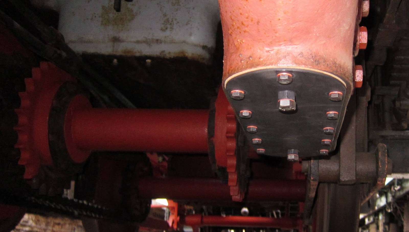
Not forgetting the 'sprockets'!
In amongst the information are the figures for the number of gear teeth and sprocket teeth. These allow an interesting calculation of speed per engine RPM.

Crankshaft pinion: 45 teeth.
Countershaft pinion: 102 teeth.

Axle sprockets: 27 teeth.
Countershaft sprockets: 15 teeth.

Engine speed to axle speed ratio:

102/45 x 27/15 = 4.08:1.

Wheel diameter: 36 inches.
Wheel circumference: Pi x 36 = 9.42 ft.

[Feet/mile = 5280].

MPH = (RPM/4.08 x 60) x 9.42/5280 = 13.1 at 500 RPM engine speed.

So we can expect Sentinel 7109 to be speeding along at 13.1 MPH when its engines are at 500 RPM!

Other noteworthy points in the orders show that there was an injector fitted originally and that no Weir boiler feed pump was included; it would appear to have been ordered and fitted later. The boiler was a single 'experimental' type as opposed to some earlier double-engined locos that had used two 100 HP boilers!

I'm also enquiring as to whether similar information is available for the two Radstock Sentinels.

Thursday, 24 November 2011

Brazed Nuts and Gear Cases

After many years of staring wonderously up into the portals under Sentinel 7109's lower gear cases, 23rd November 2011 finally saw them closed up and an oil bath created inside.
Under-frame view showing the nice pair of closed-up lower gear case portals
There are a number of requirements to be satisfied with these cover plates: they must not leak around the gasket; they must not leak around the screw threads (the holes are open inside to the oil bath); they must allow condensate to be drained off from below the oil (all of it if possible).

The gaskets are hand made from a rubberised cork material about 1/8th inch thick (3mm) using the two plates themselves as the respective templates.

Plate and cork gasket (two of each)
Preventing leakage down the screw thread is not so easy. At first, studs were tried but they were loose in the thread. These could have been secured with Loctite of an appropriate grade; however, I was concerned that the seal might not be maintained for the many years it will be required. Also, if either plate needed to be removed, undoing the nuts on the studs could loosen a stud and require it to be refitted and resealed. So I chose to use 5/16" BSW hex headed bolts with fibre washers.

[Note to me: 6 of the 24 bolts have been cut to 1/2" length for the holes which have been closed off with weld where presumably there was a problem with the gear case casting. The rest of the bolts are 1" but could be cut to 1/2" in future if wanted - unnecessary extra work!].

I'd also been recommended to use 'Dowty' washers instead of fibre; however, I had to dismiss this idea as some of the holes in the plates were not round and would allow leakage at the long end of the holes! (Offers for 25 M8 Dowty washers anyone?).

I devised a cheap method for draining the condensate using M12 nuts brazed to the underside of the plates and drilled and tapped so that a bolt could protrude right through. I milled a slot along the length of the bolts so that they could seal when tightened up but let fluid pass when loosened.

Slotted bolt and brazed nut
The key point here is that fluid needs to drain down to the surface of the plate and not allow a pool of condensate to remain that cannot be drained. One suggestion had been to use a drain cock; however, it would still need a brazed nut or threaded boss to mount it and £15 or so each is a lot more than the cost of stainless steel M12 bolts!

Use Crankcase Oil
Sentinel require Crankcase oil to be used to lubricate the gears as there can be seepage of crankcase oil through the crankshaft end bearings from the crankcase to the gear case. After some careful investigation, I selected Hallett Oils' SCC680 Crankcase oil which is designed specifically for Sentinel steam engines. It is a viscous, gloppy (onomatopoeic word) fluid that encourages any condensate to separate out and sink to the bottom (water being heavier than oil). It's this property that enables the condensate to be drained.

The gear cases needed to be filled to the second check level to suit the diameter of the gear wheel inside.

The one in the middle
At this point I realised that the gear cases were somewhat larger than I'd anticipated as they swallowed at least two gallons per side! So the plentiful stock of crankcase oil purchased for the engines is not now as plentiful as it needs to be!
Right hand Cover Plate
Left hand Cover Plate
So let's hope that I've thought of everything to prevent any leaks as draining out two gallons of gloppy oil to start again is not an appealing prospect!

Tuesday, 4 October 2011

Chuff-Synchronisation - Now what's that all about?

Richard Nixon, drawings' custodian of the Sentinel Drivers' Club and Isebrook's carer, emailed me recently with a technical query about double-engined Sentinels.

His concern was that, with two engines, if they were not coupled together so that each chuffed up their respective chimneys at the same time, instead of air being drawn up through the fire, would each engine merely suck air back down the other engine's chimney?

To understand the point, a bit more needs to be known about how a double engined loco works. In particular, each engine has its own double chimney mounted immediately above the firebox.

Twin double chimneys
Plan view of boiler showing the twin double chimneys
Single exhaust pipe divides to feed two chimneys
Blasting exhaust steam through a nozzle in each chimney tube draws air upwards through the chimney. The air should be drawn up from below through the firegrate.

This all works fine if both engines chuff at the same time; however, if they don't then air can be drawn down the un-chuffed chimney instead of up through the fire (probably being the path of least resistance). The result would be a poorer fire in times of need.

So are 7109's two engines chuff-synchronised?

I had originally thought this was true and that the two engines on 7109 were gear locked together.

A gear case on the end of each engine crankshaft
with the larger gear case below
From the above picture, it looks as if there would be a gear for each engine in its upper gear case (black, like a pair of eyebrows) meshed with the larger gear in the rusty/grey gear case below. (There is the same situation on the other side). If all these gears were in place as described, then the two engines could have been chuff-synchronised together.

However; to my surprise, when I first undid the oil filler cap in the front engine's off side gear case (the one to the right in the photo), I found that the gear case was empty. On the near side, the rear engine's case was also empty.

At first, I thought we'd been diddled but then it dawned on me. There is a sprocket for a chain to drive the front axle from each lower gear; the two gears are not linked and rotate on a fixed, 'dead' axle. Thus the engines rely on the chains being set appropriately and tightly enough to achieve chuff-synchronisation.

Twin sprockets for chain drive to front axle
It's doubtful that chuff-synchronisation was achieved particularly well in both directions due to slack in the chains.

This situation evolved in later double geared locos such as Sentinel 9622.

Sentinel 9622's drive chains
9622's chains are double width, presumably for extra strength. These were most likely adopted because of the double gearing. Depending on whether low or high gear is selected, the drive will be transferred to the front axle by one chain or the other but not both. Hence all the driving force has to go via a single chain in contrast to 7109 where both are used at the same time.

To make the double gearing work, both engines are locked together at the end of the crankshaft where the gear is engaged. This happens by having a gear in each upper casing meshed with the gear in the lower casing.

However, there is still more to the picture: double geared engines have a neutral setting in which neither high nor low gear is engaged and the engines can be run with neither load nor locking together. This enables better warming through of the cylinders prior to loco movement.

Front view showing different sized gears at each side
(Diagram derived from 1930 A2 drawing, courtesy Richard Nixon)
Side view of upper and lower gear casings
(Diagram derived from 1930 A2 drawing, courtesy Richard Nixon)
Of course, the asynchronous rotation of the two engines in neutral means that when they are put into gear, they could be in any relative state of rotation. As such, sometimes they might be chuff synchronised and sometimes not in an unpredictable manner.

So Sentinel 7109, 9622 and other double engined locos have the same problem.

There is yet another consideration and that is to do with the resonant frequency of the chimney system. This may not be relevant if the chuffing frequency never gets high enough to reach resonance and I am sticking my neck out here due to lack of in-depth knowledge of this type of system. (Ask a designer of resonant, high-performance, car exhaust systems!).


Below resonance, a chuff up one pair of chimneys could easily pull air down the other pair if out of sync. At resonance, I do not know what happens. Above resonance, the chuffing will be so fast that sucking air back in won't take place and each chimney will behave as if sealed. (I'm assuming that the chimney system behaves like a ported loudspeaker enclosure).

So the conclusion to all this? I think we'd better just try it and hope for the best!

Tuesday, 27 September 2011

Sentinel 7109's Lower Gear Housings

Since July 2011 (now September), I've taken some better photos for this article so here's the new 'enhanced' version!

Three new inspection bolts have been made for the level check holes in the lower gear housings.

Inspection bolt with blind axial hole and linked radial aperture
for oil level checking
The bolt is partly removed to check if oil comes out of the radial aperture
View from above
So why three level check holes and not just one? Simply, it depends on the size of the gear wheel inside. Sentinel offered the ability to change the gear ratio to suit each customer's haulage and speed requirements.

7109 was set up for slow, heavy haulage (I'm guessing here but it will be obvious in due course); hence it will have a large gear in the lower gear case. As a result, it will not need such a deep oil bath as one set up for higher speed with a smaller gear in the same place. So the the check hole actually used will be to suit the expected oil level inside.

Going off-subject for a moment, the Teifi Valley Railway visit on 18th September 2011 revealed an interesting angle on this with the double geared Sentinel 9622 built in 1958. Have a look at the next two photos:
Near side lower gear casing (9622)
Off side lower gear casing (9622)
Note that the drain cock (posh way of doing it) on the near side is on the middle level whereas, on the off side, the drain cock is on the top level. At first, this seems to be a mistake; however, it is a double geared loco with different sized gears in the near and off side casings. Hence a different oil level is needed for each. (It's inevitable that however many photos are taken at the time, something else needs to be illustrated when the time comes. Anyway, hopefully these are just about good enough to illustrate the point).

Also noteworthy in the 9622 photos is that bolts rather than studs/nuts are used to fix the plate in place.

Does anybody know what that big nut-like thing is in the middle of each cover plate? I guess it's a means of draining condensate from the gear case but it was so covered in green slime and it was raining hard that day so I didn't feel much like crawling about underneath and cleaning it up to find out!

A final noteworthy point: in the bottom right of the off side photo can be seen a drive chain. 9622 has double width chains whereas 7109 has single. The double chains would have been used for extra strength as, with double gearing, the drive would be only via the left or right hand chain depending on whether high or low gear was selected. 7109 has one single width chain per engine.

Back to 7109: the new gear housing bottom plates are under construction in preparation for crankcase oil to be added. Hopefully the oil will dampen the unceremonious 'clanking' heard when running on compressed air without a load.
The bottom plate goes here
Crankcase oil is a special type designed for Sentinel steam engines. Its specific characteristic is that water condensate separates out and sinks to the bottom easily for draining off.
Definitely Crankcase oil required!
When fitting 7109's gear case bottom plates, a gasket will be required between the plate and the housing. Hexagonal headed screws will need to be used with fibre washers to hold it in place as some of the holes into the housing are open to the oil contained within; without fibre washers and fixed-head screws, the oil will be able to seep out via the thread in the housing and the thread in the nut and possibly also between the nut and the bottom plate.
Related Posts Plugin for WordPress, Blogger...