Tuesday, 26 November 2019

Steam Heating (3)

Following on from Steam Heating (2), I've fitted the carriage warming equipment to Sentinel 7109 ready for a steam test with a train in a few days time.

I began with the boiler connection and isolating valve.
Isolating valve plumbed into the boiler orifice
Having removed the boiler orifice plug and cleaned out the threads, I checked the 1/2" BSP thread type using a parallel tapping tool. The thread was clearly a parallel type and the BSPT tapered thread of the hex nipple was loose unless tightened firmly. This was as expected so I converted the thread to a tapered type using a tapered tapping tool. Now the BSPT tapered thread of the hex nipple fitted much more positively.

I completed the joint using Rocol steam seal. Total loco unavailable time: about half an hour!

I then fitted the standard buffer beam equipment using the purpose-designed flange.
Standard buffer beam equipment fitted to buffer beam (1)
Standard buffer beam equipment fitted to buffer beam (2)
The blue Spirax Sarco Pressure Reducing Valve (PRV) and Safety valve assembly came next followed by the flexible hose to link the isolating valve to the buffer beam equipment.
Blue PRV and safety valve attached to rear of flange (1)
Blue PRV and safety valve attached to rear of flange (2)
Also showing above is the narrow copper pipe to link the buffer beam outlet pressure to the gauge on the cab's rear panel near the roof on the fireman's side.
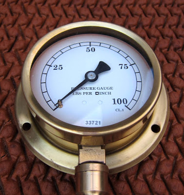
Steam Heating Pressure Gauge
The weight of the PRV assembly is supported by a clamp between the PRV and safety valve linked to the footplate above by M10 studding.

Having fitted the buffer beam equipment and attached the hose, I hitched up the hose end using the standard support links. It then became obvious that the assembly was somewhat lower than expected. On examining a MK1 carriage for comparison, the assembly is 6 to 8 inches lower.
Hitched with shortened support linkage
To avoid the end dragging on the ground or catching the rails, by wiring the two end parts of the support links together, I've pulled it up to a safe height above the rails as shown above. A more permanent version will be devised in due course.

Prior to steaming, the first test was to to check that the lower height would not prevent a connection being made to a carriage. As shown below, it is all OK.
May be low but fits perfectly.
Now all we need to do is a steam test. I anticipate that the carriages will be too cold, too hot or somewhere in between. If these are the pass criteria, then all should be fine!


Wednesday, 13 November 2019

Steam Heating (2)

After some pretty hectic weeks, I have most of the sub assemblies ready to fit. Rapid progress has been made possible by Amanda and Rob at South West Engineering Supplies at Bumpers Farm industrial estate near my home in Chippenham. Without them, I'd have been struggling to obtain all the bits and pieces in a short time and they have given me ready access to trial and error items. So a big thank you to them.

Following on from 'Steam Heating (1)', this is how it's developed.

What equipment is needed?

1. High pressure pipework and an isolating valve able to withstand the Sentinel boiler temperature & pressure (212DegC & 275psi).
High Pressure Pipe Fittings and Valve
In the photo above, the steel 'T' fitting's leg links to a 3000psi stainless steel union and thence to a taper threaded hex nipple which will screw into the boiler orifice. This union allows the angle of the 'T' to be set after securely fixing the nipple into the boiler orifice. The plug at the top of the 'T' fitting is to provide another steam outlet for future use.

The second union below the 'T' fitting allows the valve to be orientated appropriately. The valve is a three-part ball valve made by Valtac. I've written about these before. The hex nipple below the valve will connect to flexible braided hose to take the steam down to the buffer beam. Although the nipple in the photo is a steel type, I will be using a parallel threaded hydraulic fitting machined to take a copper washer sealed mating connector.

2. Pipework to carry the boiler pressure steam to the buffer beam apparatus.

Purists might criticise me for using modern flexible stainless steel braided hose instead of copper pipe with braized end fittings. I can order and receive the flexible hose with welded end fittings and a pressure test certificate within a week and be confident in the result. Using copper pipe, I cannot do this. (In fact, the hose arrived in four days!).

I've covered this before in detail here.

3. A pressure reducing valve to take the boiler pressure down to the carriage requirements (about 40psi).
Blue Pressure Reducing Valve (centre) (and one assistant)
Blue Pressure Reducing Valve (and other assistant)
The blue Spirax Sarco PRV is a 1/2" BRV2S with a Green Spring to allow a range of 20-60psi.

Arguably, to reduce the length of high pressure hose, I could have put the pressure reducing valve below the ball valve instead of behind the buffer beam. However the PRV needs to be mounted upright and would have taken up too much space in the cab.

4. A safety valve to prevent exceeding the carriage maximum pressure.
Gunmetal Safety Valve
The safety valve is a 1/2" ART 642 type made by Albion.
Safety Valve Detail including 3 bar setting.
5. A pressure gauge to allow the carriage pressure setting.
3" Steam Pressure gauge
The safety valve has been delivered certified to 45psi (3 bar) so 100psi full-scale is fine. I purchased it new from "thegaugeman61" on Ebay".

6. Heavy duty bracketry to fix the pipework and standard buffer beam equipment to the buffer beam itself.
Flange made to fit the standard buffer beam equipment to the buffer beam
The flange's central hole is tapped to 1.25" BSPT (tapered) to take a 1.25" section of pipe. The pipe section is then held by a Stauff clamp with an add
itional supporting bar screwed to the bottom edge of the buffer beam. A third bolt fixes the flange through the buffer beam. It is pretty strong and intended to survive heavy handling.
The flange 3-point mounting to the rear buffer beam
The Complete Assembly

I've pre-assembled the 'flat-pack' version of the equipment to show it all together before it disappears out of sight in and under Joyce's metalwork.
Complete 'flat-pack' and assistants
The boiler fitting is at the top. It passes steam via a 'T' fitting to a ball valve and thence to the braided flexible hose. The hose links to the blue PRV which passes lower pressure steam to the safety valve and pressure gauge pipe. Finally the pipe connects to the back of the flange and to the standard buffer beam equipment.

Now all I have to do is fit the kit and test it. Initial fitting will be quite quick for test purposes. I'll clamp the pipework properly when I'm happy it performs satisfactorily. The assistants will not be allowed on site at Midsomer Norton as they haven't passed their Personal Trackside Safety exam (honest!).

Thursday, 10 October 2019

Steam Heating (1)

Carriage Warming Steam Hose link
I've been asked by the Somerset & Dorset Joint Railway Co. Ltd. to fit steam heating, aka carriage warming equipment, to the cab end of Sentinel 7109 'Joyce'. I'm slightly bothered by the idea as the gear involved will take up even more of the already limited cab space. However, I will give it my best shot, hopefully in time for the cooler weather coming on.

There are some critical feasibility questions:

  • How much steam is required?
  • Does the boiler have the capacity?
  • Where can I tap-off the steam supply?
  • What size of pipework is needed?
  • What equipment is needed?
  • How to minimise the out-of-service time during installation?
  • How to ensure the installation is safe?
  • How do I test it?
How much steam is required?

In 2014, the Heritage Railway Association (HRA) produced a Steam Heating Apparatus guidance note which I am using as the authoritative document. It states the following:

"Most steam heated coaching stock contains thermostatically controlled heaters which limit the steam consumption once the heater has reached working temperature. Because of this and the reduced length of trains now running, a pressure of 40psi is sufficient to maintain a flow to the end of a rake of vehicles. Allow about 80-100lbs of steam per hour per carriage to heat a train."

As a worst case, I'll assume Joyce will need to provide 100lbs of steam per hour per carriage.

At Midsomer Norton, Joyce is generally limited to two carriages although she could encounter more if operated elsewhere. I am thus basing calculations on three carriages and deem the requirement to be 300lbs/hour.

Does the Boiler have the Capacity?

Joyce's boiler has the capacity to produce 4600lbs/hour. Thus only about 6.5% of the boiler output would be used when supplying the 300lbs/hour to the carriages. I doubt if Joyce would notice this and if it did hold her back, the heating could always be turned off while climbing the 1 in 50 hill from the station, usually for about 5-7 minutes.

Where can I tap-off the steam supply?

Joyce's entire boiler output has to be able to be passed through the safety valves. The manifold which supports the safety valves is fed through a 3/4" diameter orifice. This means that 4600lbs/hour can pass through a 3/4" orifice.

There are two 1/2" diameter plugged orifices near the top of Joyce's boiler, one on the left and the other on the right hand side. A 1/2" orifice has 4/9ths of the area of a 3/4" orifice. Thus it is easy to say that 300lbs/hour will have no difficulty with a 1/2" orifice.

I plan to use the left side orifice as it will allow the fireman to control the heating. I will also use a plugged 'T' pipe fitting to make it simpler to add a steam wand later.

There are some other options I dismissed:

1. The super-heater input manifold at the front of the boiler. This would require removing the coal bunker to get access and would put an isolating valve out of the reach of the footplate crew.

2. The regulator assembly. This would have supplied super-heated steam complete with cylinder oil - I'm not sure how hot the passengers really want to be in cold weather!

3. The right hand 1/2" orifice. This would add to the already heavily populated driver's side of the cab and it's really the fireman that should be in control.

4. The safety valve manifold/fittings. Same as in 3 above but could well make for a lengthy down-time during installation and require the disturbance of well proven installed items.

Note: references to 1/2" or 3/4" are to nominal inside pipe diameters and the BSP thread size.

What size of pipework is needed?

Using a 1/2" boiler orifice indicates that 1/2" pipework will be adequate and it is good news as 1/2" pipework won't fill too much of the limited cab space.

I was surprised at this but the figures tell the story. However, as we are only allowing for 3 carriages, not 14 or so as might have been the case in the days of British Railways steam, I am convinced 1/2" pipework will be fine.

What equipment is needed?

I'll cover this in a subsequent article as it will be quite extensive.

How to minimise the out-of-service time during installation?

The only part of the installation work that will actually make Joyce unusable is when making the steam connection to the boiler. The rest of the apparatus can be fitted to Joyce before making the boiler connection without disturbing the ability to operate.

How to ensure the installation is safe?

The critical part of the apparatus is the link from the boiler orifice to an isolation valve fitted as close as possible to the boiler.

Either a male parallel threaded fitting sealed with a Copper washer will be used to connect to the parallel female thread of the boiler orifice or, preferably, both tapered male and female threads as they lock more effectively. Tapered male threads with parallel female threads are not suitable for this application as they have a limited contact area with the female thread and are not as strong.

Heavy duty forged steel or 3000psi Stainless steel fittings will be used where full boiler pressure is involved. Malleable iron fittings will be used at carriage pressure.

'Red-band' grade steel pipe or braided/annularly corrugated flexible hose or a combination of both will be used.

The isolation valve will be of the same type used for the vacuum ejector isolator, whistle/pressure gauge isolator and blown-down valve. These are high grade carbon fibre reinforced PTFE-sealed stainless steel ball valves as previously described here.

How do I Test it?

I'm not planning any special equipment to test the new apparatus. Instead, it will be a matter connecting Joyce to a three carriage train and trying out various functions.

1. With the hose link valve closed so that steam cannot leave the loco, initially turn on the isolator valve; the out-going pressure should not exceed 45psi. A safety valve should open to prevent it going higher than 45psi (3 bar).

The pressure reducing valve's pressure control should be varied to show that the outgoing pressure can be set as desired. (It may not be possible to do this without a flow of steam. If this is the case then it should be done carefully with the valve to the carriages open).

2. If not already done so, open the valve to the train and check the loco can supply the required pressure to the three carriages when all their heaters are set to maximum.

3. Check that the set pressure can be maintained with the boiler pressure between 100 and 275psi. Experience with the vacuum brake ejector pressure reducing valve suggests that as the boiler pressure reduces, the outlet pressure may rise but not above the safety valve setting.

Wednesday, 7 August 2019

Improved Oiling for the inter-axle Chain

Whilst I've written extensively about Sentinel 7109's front drive chains, I've said very little about the chain which links the two axles. It does the job more conventionally performed by connecting rods. The chain was in place when Joyce arrived in 2004 and I've largely just left it to get on with its job.
Highlighted original oil pot and down-pipe with wipe-rag
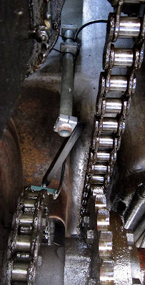
Oiling the chain was originally done by gravity. A pot fed oil down a tube to the chain via a rag which wiped oil on the links as they moved past.

The oil pot was another example from Joyce's missing items portfolio so I had to construct a new one. I used the end section of a small argon gas cylinder and added a valve to turn the flow on and off.

These items are hidden in the photo below beneath an upturned metal cover (OK, it's a bean can but it was a perfect fit!). The down-pipe is original but the new rag was a hem extracted from an old pair of jeans.
Gravity-fed oil feed
In so far as it went, it could do the job just about adequately but I was forever either forgetting to turn it on before moving off or leaving it on when stopped so one link got deluged and the rest left dry. (Perhaps the original pot used a wick?). What was really needed was a similar system to the front drive chains such that oil would only be provided when moving.
Being driven by the engines, the mechanical lubricator was an ideal candidate but its four pump barrels were already allocated.
Mechanical Lubricator (before restoration)
In the above view, the right hand pump feeds the near-side drive gear bearing and the next one feeds the off-side drive gear bearing. The third from right feeds the steam supply and the left hand one feeds the front chains via a pair of drip trays.
Drip trays and drip feed tubes
Initially I thought that the mechanical lubricator was out of bounds but experience showed that a good supply of oil was already being fed through the drive gear bearings into the drip trays without any additional oil required from a dedicated pump. Thus the left-most pump was effectively a spare.

In the back of my mind has always been the thought that 7109 was a prototype and thus some parts/methods of operation were possibly experimental and not well tried and tested; they could thus be improved.
Oil from the gear bearings into the drip tray
I set out to construct a feed from the mechanical lubricator to the inter-axle chain. My plan was to suspend a three-drip device above the chain and connect it by a pipe to the lubricator.

A number of parts needed to be made:

1. An adaptor to connect a pipe to the lubricator pump.
2. The pipe itself (I chose to cheat and use rubber fuel hose).
3. The three-drip device.
4. Rigid support for the feeder so it wouldn't shake it all about.

The adaptor seemed an easy task: it would be needing BSP threads obviously? No it wouldn't! To cut a long story short, it needed a rare British Standard Cycle thread as used on push-bikes and motor bikes. The thread was actually 3/4" 20tpi and taps and dies were surprisingly easy to obtain (Ebay).
The rubber hose adaptor rightmost
The adaptor consists of a coupling with a female 3/4" BSC thread end to end and a plug screwed into the top. The plug is tapped for a standard 1/8" BSP hose adaptor. The coupling is screwed on to the pump first. The plug seals against the top of the pump with a fibre washer. Heldite was used to seal the hose adaptor.
Three-drip device
I wanted to be able to set the three-drip device so that it would dribble on the left and right links of the chain as well as centrally on the rollers. Thus it would be required to be able to be rotated to get the drippers the right distance apart and in the right place.

Any resemblance in the body of the device to a Lidl compressed-air adaptor are purely coincidence of course (but it saved a lot of work for very little cost!).
The dripper attached to an angle-iron support
The complete dripper support
I made the rigid support using a pair of Stauff clamps to fix a vertical piece of 1.25" steel pipe (same as used for the vacuum braking pipework) to the front of the water tank inside the engine compartment.
Pipe clamped to the water tank
I then attached the angle iron support bracket to the pipe with another Stauff clamp.
Viewed from underneath
Stauff clamps grip the pipe very tightly and the dripper is held very robustly in place.
Not an easy photo so take (apologies for low quality)
The rubber pipe is supported in a fairly low-tech manner.
Rubber pipe routing
After a lengthy non-trivial design and installation task, I tried it out on a passenger operations day. It certainly works and there is now no shortage of oil for the drive and inter-axle chains and one less job to do when preparing to steam. There is still a good deal of fiddling about to do yet to get the flow rates right, not helped by the newly sorted central heating for the mechanical lubricator. The oil is now warmer and thinner as a result and the pumps provide more oil than before.

One question I don't have the answer to is how much oil does a chain need? I haven't oiled my mountain bike's chain for years and it is still happy; however, these chains work a little harder than my bike's so sufficient will be enough.

I'm also hoping to reduce the oil consumption. 7109 uses about 3 pints of cylinder oil a day - that seems a lot to me.

I'll remove the old gravity-feed oiler when all is set up satisfactorily.

Grate Solution to a Problem

Not widely known but just before the press were due to arrive on a steaming day recently, Joyce's firebox centre firebar dropped into the ashpan - not really what's wanted with little time to put it right and in the middle of a raging furnace!
Complete Firegrate;
However, miracles can be performed when there is no choice and the fireman of the day managed to put it back in place and all was well.

It's easier to empty ash/clinker from the grate by removing a firebar but getting it back in isn't easy without crawling underneath (ideally with the ashpan removed)(decidedly not my favourite activity).
It's Grate
Although it won't be much help with replacing a dropped firebar under a hot fire, I've made a tool for putting them back through the firehole after emptying the grate when cold.

One end fits through a firebar slot and the curved end is for twisting the firebar into position.

Tuesday, 6 August 2019

Mechanical Lubricator's Central Heating

It was April 2013 when I last wrote about 7109's mechanical lubricator. I'd been concerned that the heating system using exhaust steam had not been working although it didn't seem to be a significant problem.
Aluminium heater (centre top of photo)
Exhaust steam is fed to a blind Aluminium tube fixed into the bottom of the lubricator underneath the four pumps. The idea is that the steam condenses giving off its latent heat to the lubricator and the condensate drains via an external hole in the fitting.
Aluminium Heater close-up
Recently 7109 was running without the near-side engine covers in place and somebody pointed out that steam and water were being sprayed all over the rear engine when moving. On inspection, the spray was coming from the condensate drain hole.

Not having given the subject much thought, I'd originally installed the heater with the drain hole pointing upwards and this was the cause of the spray. It had also not caused me any concern because, for a long time after I'd had trouble with gland packing disintegration, the exhaust steam feed pipe to the lubricator had become blocked with the spifflicated packing. Thus the spray only became obvious when I unblocked the feed pipe.

Unfortunately, the PTFE washer used to seal the heater had worn such that I couldn't just rotate the heater and so it all had to come apart to do the job properly.
Corrected down-facing condensate drain hole.
The squashed white item is the new PTFE washer.
Disassembly does have the advantage that it gives an opportunity to do other bits of maintenance. In particular, it had always been impossible to see the oil level in the sight glass as the glass tube itself was dirty. I hadn't originally had access to a parts washer but I now it is an invaluable tool for cleaning such items and the result is below.
Newly cleaned level sighting tube
It does show the level (I tightened the leaky seal later)
To tighten the tube, the lubricator's lid fixing bolt above the sight glass has to be removed and a tapered flat-blade screw driver used to turn a hidden grub-screw. Removing the grub-screw allows the glass tube to be removed.

The top and bottom of the glass tube had originally been sealed using leather washers; the leather had deteriorated so I used a pair of fibre washers instead.

Oil consumption now seems to have increased, no doubt due to the oil being thinner at the raised temperature.

Saturday, 3 August 2019

Finding Joyce & Joyce

Joyce Helen Sandeman (1902-1974) aged about 12
When Sentinel 7109 first arrived at Midsomer Norton in December 2004, I and the other seventeen original owners were unlikely to have envisaged the human interest that would come to light many years later.

As prototype to the two Radstock Sentinels, Sentinel works number 7109 ‘Joyce’ had worked at Croydon Gas Works from 1927 until 1960 prior to transfer to Bressingham Steam Museum in 1968 for use in preservation. But, in those 33 years of working life, ‘Joyce’ had amassed a history of her own.

I’d been aware that in 1927 ‘Joyce’ had been named after Joyce Helen Sandeman, the only daughter of the Croydon Gasworks Chairman William James Sandeman OBE.


I discovered that Joyce Helen had been born in 1902 and died in 1974 and that the naming was late in 1927 but it seemed odd to me that a loco would be named after an adult of 25 rather than a beloved child aged between maybe 5 and 15.

A clue was found in that Joyce Helen was described as ‘incapacitated’ in the 1939 registry whilst residing in a care home in Caterham. Thus I speculated that she had either been born disabled or become disabled before she was 25.

Through searching Ancestry.co.uk, I found that Joyce Helen had died a spinster with no siblings, nor any children, although her father had seven brothers and sisters. Thus, somewhere out there would be living distant relatives of Joyce Helen albeit of subsequent generations. I left it at that in 2016 but this year I determined to continue the search initially via local Croydon newspapers.

Before I had a chance to get started, astonishingly, in January this year I received an unexpected phone call from Ian Hocken who told me that Joyce Helen was his great aunt.

We were both very excited at having made contact. Ian told me that he had been at a family gathering last Christmas and the subject arose of great aunt Joyce’s steam locomotive and what had happened to it. So they did an internet search and found my 7109 blog and tons of YouTube videos of ‘Joyce’ in action.

It’s difficult to imagine how they must have felt at the discovery but Ian said they were absolutely gobsmacked. We discussed a little about the family and I was pleased to find that there are still two relations with Joyce Helen’s surname ‘Sandeman’: Elizabeth, who is in her 80s and Jenna who is 18.

After some searching of family albums, Ian sent me four scanned photos of Joyce Helen at ages of about 5, 9, 12 and 25. In the first three, she is a delightful and pretty young girl and clearly enjoying life (Photo). However, at 25, something terrible had obviously happened to her and she is visibly incapacitated. It’s a sad photo but it quashed my speculation that she might have been disabled from birth.

In April, I travelled to Ian’s home in Reigate to meet him and other relatives. I had a wonderful day and was made to feel like a member of the family – we do have a common relative in ‘Joyce’, of course!

Collectively, we don’t know what actually happened to Joyce Helen. A hundred years ago, people did not recover from illnesses that we now consider minor. Of course, WW1 could have played a part and Croydon did suffer bombing at that time. One day we’ll find out, perhaps.

I never thought that when I set out to restore a steam loco that it would lead to finding a new family but, on Saturday 27th July 2019, they came to visit Midsomer Norton station to see and ride behind ‘Joyce’.
Ian Hocken, Jenna Sandeman, Andy Chapman, Elizabeth Sandeman (Photo: Gail Coleshill)
It was an exceptionally enjoyable gathering preceded by an interview on BBC Somerset and attended by many local press and some of the volunteers that had contributed to ‘Joyce’s’ restoration.

I framed a dedication to Joyce Helen and presented it to Ian and Elizabeth on the day.

A Tale of two Joyces
Jenna, Ian, Elizabeth & Andy (Photo: Peter Nicholson)
I wrote a previous article about Joyce in December 2016 which can be found here: http://sentinel7109.blogspot.com/2016/12/who-was-joyce.html. Much of it has stood the test of time.

Saturday, 23 March 2019

Painting by Numbers

Sentinel 7109's cast Aluminium front 7109 plate has been looking rather sad until recently with the black paint becoming somewhat flaky.

So here's a little sequence of renewal photos.
Cleaned-up and primed with 'E-Tech Technik Self-Etch primer'
(Must be good with a name like that).
Re-blacked using 'Baufix Metal Paint with rust protection'
(I bet it won't rust).
And finally renumbered using water-based Antique White acrylic.

Saturday, 2 March 2019

Wear & Tear (3)

A quick update on Wear & Tear (2).

I've replaced all three joints from the steam end of the Sentinel 7109's cab mounted boiler feed pump; these are the ones above and below the valve chest and the failed one sealing the end cover. The valve chest ones were undamaged but I replaced them anyway to improve long term reliability.
Light green layers replaced by the dull grey graphite of PSM150/AS
When the pump's end cover joint failed, for unknown reasons steam got into the water end of the pump. This has happened once before and I've never worked out the cause. I can speculate about the check valve to the boiler getting wedged open to allow hot water back into the feed pipe but I don't actually know.

Perhaps the check valve could stay open if the feed water and boiler water were at identical pressures? This is not likely as there is a spring to help the check valve to close. This mystery remains on the 'too difficult' pile. I checked the cleanliness of all three check valves for peace of mind and found no cause for concern.

Not only did the steam get back into the pump's water cylinders but also further upstream in the pipework towards the water tank feed. I mention this because I'd just painstakingly replaced it all (click here) after the frost damage to the original water valve. Being a water feed, I again used 'Heldite' as the thread sealant as it was well in spec for cold water and low pressure.

However, it's not designed for high pressure steam! The result was that the pipe joints were emptied of the Heldite and no longer doing their job.

I've rebuilt the pipework again; this time I've used Rocol's 'Steamseal' as the thread sealant. The name gives it away so next time it should withstand a steam ingress where it's not wanted.

The water cylinder piston rings are made of a fibrous non-metallic material. (click here for more detail). They survived steam ingress the previous time and seemingly this time also as the pump worked well when tested with compressed air.

Wednesday, 27 February 2019

Wear & Tear (2)

After three years of reliable service, Sentinel 7109's cab boiler feed pump decided it was going to play games and started spitting steam out of the steam cylinder end cover joint.

This early photo shows the light green layer between cylinders and the end cover.
June 2011 photo long before putting the pump to work
The material I used for the joint was Klinger's Klingersil C-4400. I'd bought this in 2010. Its spec shows that it can withstand about 23bar pressure at 230degC. All seemed satisfactory as water boils at approximately 230degC when at 19bar pressure.

The next photo shows the effect of three years' use (and possibly the recent heavy frost?).
Comprehensive disintegration of the joint material
There are splits in many places which makes me wonder if there may have been some frost involved but that is speculation.

In retrospect, what is more to the point is that, while the spec shows the joint material is good for 230 degC and 19bar, the steam supply to the pump has passed through the superheater and is likely to be somewhat hotter than the figure I had originally assumed. I'm thus rather surprised it had lasted as this long!

Later in the restoration process, for all steam joints, I'd switched to a higher spec joint material, namely Klinger's Kingergraphite PSM/AS. More details here.

So that's what will be used for the repair.

I can say I now have more (hard-earned) experience!

Monday, 25 February 2019

Wear and Tear (1)

Sentinel 7109 has been hauling trains for nearly three years now and inevitably pulling 75 tons of carriages repeatedly up a 1 in 50 hill is going to ask a lot of a little engine.

Late in 2018, from time to time a knocking noise was heard from underneath and investigation showed that the main steam pipe had lost some insulation due to abrasion against a support bracket.

At the front of the water tank and just behind the rear engine, I had reinstalled the main steam pipe and included a support bracket using (from memory) existing mounting holes.
Main steam pipe with bright red support bracket.
The main steam pipe connects the regulator body to the 'Y' pipe fitting in the engine compartment. As far as I can tell from photos I took in 2004, there were no support brackets for the main steam pipe between its ends. This did not seem satisfactory to me and hence the addition of extra support.

However, not everything works out quite as anticipated and the bracket had been wearing the insulation allowing hard surfaces to knock together. The pipe clearly moves about when Joyce is in motion.
Worn insulation
On removing the bracket, it appears that the wear had not abraded the actual metal of the pipe but I'm glad I found it now and had not let it get any worse.
Metal exposed beneath the bracket location
It would appear that the bracket was too restrictive and probably with too small an area in contact with the pipe. However, I still want the extra support but with more give than it had.

I've wrapped some Aluminium-clad fibre glass sheet around the bracket to cushion the support from the pipe so that it is supported but not clamped.
Fibre glass cushion
Now to see how it behaves. (I have some other ideas if this doesn't last).
Related Posts Plugin for WordPress, Blogger...