Showing posts with label Testing. Show all posts

Friday, 29 April 2016

Glandular Diversion

My recent article, 'Glandular Fervour', showed the gland packing replacement task ahead. However, prior to that, I had a little idea to temporarily prevent the leaked water ending up in the crankcase.
Grommet
By wiring a grommet around the pump shaft to just the right tightness, hopefully, with the shaft well greased, any leakage should be diverted away from the lower gland and out to the drain.

Fingers crossed!

Post script:
The grommet idea worked quite well particularly when the grommet was well above the lower gland.

Tuesday, 26 April 2016

Glandular Fervour

In February 2016, when Sentinel 7109 took its first self powered trip in decades, it was clear that there were a few problems. One being that the various glands which seal piston rods and pump plunger shafts have gone hard or have been overtightened in ignorance recently or in the past.

There are 18 of these associated with the two engines and their boiler feed pumps. Some are worse than others, particularly the pump glands which are letting water out and down into the crank cases. Whilst crankcase oil is designed to allow the water to separate out from the oil and be drained, I'm not sure it was designed to cope with gallons of water!

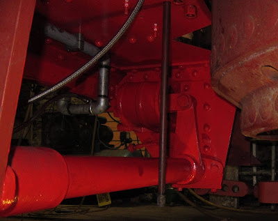
These photos are from April 2009 and show the state as found of the front engine pump glands.
Glands within the pump assembly
There is an upper and lower gland, one should prevent water leaking downwards from the pump, the other to prevent water that did leak from entering the crankcase below.
A bit Rusty?
It's difficult to tell whether the rust had accumulated during use 50 years ago or subsequently.
No better from this angle!
After much restoration, the front engine pump glands are shown operating in this video clip on YouTube. (Sorry, it's too big to include here).

Clearly there is work to do! I took apart the rear engine's upper pump gland and poked in the camera to see how it was.
Rear engine's upper pump gland
The gland material looks pretty hard with a small gap around the plunger. This will have to be dug out and replaced before it will work well. Fortunately the shaft seems to be fairly parallel so it may not need replacing. Anyway, it's easier to try a simple fix before a complicated one so I'll do the packing only to begin with.

I've been recommended greased hemp rather than graphite or PTFE for water pump applications. It needs to be 3/8" square section. Sentinel used to have an off-the-shelf item for this but it doesn't seem to be available any more for some strange reason...!

Wednesday, 24 February 2016

Testing Times (1)

Tuesday 23rd February 2016 was an important day - the day an inspector called. In this case Peter Hawkins the boiler inspector.

It had been a busy few weeks leading up to this but essential to be ready for action on the S&D 50th anniversary of the line closure on March 6th 1966.

There were various tests: A general inspection of paperwork covering materials used, certificates of conformity and calibration; a hydraulic test to 1.5x working pressure (412.5 psi) to check boiler fittings were attached properly; a maxed-out steam accumulation test to abuse the boiler and check the safety valves could cope; a test of the ability to keep the boiler filled with water under maximum output conditions.

Giving the clouds a shock!
If you are wondering what Sentinel 7109 sounds like when being steam tested, try this video clip: (Higher def. on YouTube)
We also tried a less formal haulage test on the 1 in 53 gradient as in the following video clip (Higher def. on YouTube):
There are interesting times ahead!

(And it passed the tests too!).

Thursday, 18 February 2016

Rebirth of 7109!

Blessed with brilliant cool and bright weather, Thursday 18th February 2016 was the beginning of a new life for Sentinel 7109 when she emerged from the shed at Midsomer Norton station 56 years after her retirement at Croydon Gas works in 1960.
This video clip says it all (Better resolution on YouTube).


The 'beeps' in the background are the shed's smoke alarms giving their salute!
Back into life
A picture speaks louder than words.

Tuesday, 9 February 2016

Steamy!

48 years since Sentinel 7109 was last believed to have been steamed (and 56 since it was definitely known to have been steamed), finally a fire has been lit in the grate of this unique double-engined Sentinel locomotive.
Steam rising


An early start on Tuesday 9th Feb. 2016 saw Andy Chapman, Nigel Dickinson and Graham Findlay (with a cameo appearance from Justin Goold) applying the match at 08:30am.
Oily rag activity
Activity began slowly.
Slow start
A whimper from the rooftop:
Fumes fuelled the fire
Raging inferno in the making
With commensurate reaction from above.
Quadruple chimneys' worth
And more fuel for the fire.
A handful of coal
With more reaction from above.
Close atmosphere developing
Not such a cold day after all.
A nice fire to sit by
But getting a little foggy inside!
A real pea-souper!


Inevitably a new machine brings its own noises. The cab-mounted Worthington-Simpson steam driven water pump gets some exercise - what a wonderful sound! (Also on YouTube).


A brilliant day of progress and a joy to see and hear 7109 coming back to life with enthusiasm!


Note: water hoses and fire extinguishers were close at hand during the whole operation.

Wednesday, 3 February 2016

Certified Gauges

Perhaps not a particularly gripping subject but important all the same. Sentinel 7109 has two steam pressure gauges and a vacuum brake system vacuum gauge; all of these are 'previously owned' and far from new.

All three gauges were initially taken to Brunel Metrology Services Ltd in Paulton, near to Midsomer Norton. The vacuum gauge passed first time but the two pressure gauges failed - not what was wanted but not surprising for vintage items.

Brunel Metrology make use of the S M Gauge Company in Fishponds, Bristol, for more demanding calibration tasks. To save time, I took the two gauges to SMG myself.

In a few working days, a phone call came to say the gauges were now calibrated to within 1% so I collected them the same day.
Within 1%!
Calibration certificates have now been issued for all the gauges and one is shown here as an example.

It was a pleasure to work with both Brunel and S M Gauges and I would recommend either for gauge calibration services. Many thanks to them both for their helpfulness and rapid turnaround.

Saturday, 9 January 2016

Chuffed (1)

Following on from my last article, Thursday 7th January 2016 also saw Sentinel 7109's boiler with 60 psi of air in it from a (somewhat fatigued!) compressor.
Boiler Pressure Gauge on cab front
The gauge gradually climbs off zero after a while.
60 psi (ish)!
Then... the regulator can be opened for the engines to turn, the cab's boiler feed pump operated, the blower blowing (it's hard to turn it off!), the whistle sounded, the steam brake operated and (blow me) 21" of vacuum on the train brake vacuum gauge.

Have a listen to this (visually not very interesting) video clip:

Does that sound good?

Streuth! I think it's going to work!

Sunday, 13 December 2015

Steam Brake Air Tested

In June 2012, I last wrote about Sentinel 7109's steam brake cylinder. Time passes and I've learnt that restoration is not a rapid activity!

The brake cylinder was reinstalled on Monday 7th December 2015 and here it is in place bolted to the left hand frame member to the rear of the boiler. (Bearing in mind that I can only just lift the cylinder on my own, getting it into place under here was not a straight forward exercise and required a selection of trolleys, levers, bits of railway sleeper and a lot of ingenuity to get it home!).
Brake Off
Spot the difference!
Brake On
To see it in action, here's another of my little video clips (Also on YouTube).

Sounds like heavy breathing!

The testing involved connecting a compressed air supply to the Driver's Brake Valve (DBV) inlet. Movement in the video was controlled using the DBV itself as would be normal practice with a steam supply.
DBV Top Left
The brakes still need to be adjusted but that can't happen until the front drive chains are in place and the axles located for the correct chain tension.

Checking back over the 'blog, I've not been able to find anything on the Driver's Brake Valve itself. I've had the photos since December 2012 but they slipped through the net.

The Driver's Brake Valve has an operating shaft and three connections to it - the steam supply inlet from the boiler; the outlet to the brake cylinder and a drain to atmosphere to release the pressure on the cylinder piston to let the brake off after application.
DBV connections
DBV Operating shaft
The operating shaft is extended across the rear of the cab to allow the brake to be operated from either side.
Dual Controls 1927 Style!
I took the following photo just after taking co-ownership of 7109 in 2010. A few bits & pieces had been removed and examined ('played with'). There was a long journey ahead!
DBV in October 2010
For completeness, here's the Sentinel factory drawing of the DBV. It is a general drawing showing that it could be operated from either end although 7109 did not use it that way.
Sentinel DBV Sectional Drawing
Other locos mounted the DBV in the centre rear of the boiler with handles either side.
DBV in Sentinel 9599 (William Mk1)

Friday, 21 August 2015

Vacuum Braking (14) Testing (1)

Now things are starting to get interesting. Testing is where you find out what you got wrong and get the chance to put it right.

Putting it right is best done by first privately figuring out how to do it and then showing onlookers what is wrong but apparently instantly coming up with the solution. It's best done this way; nobody notices if you get it right first time!

The first simple test is to show that the vacuum pipework does not leak excessively. (In actual fact, it does not matter if the system leaks but it does matter if it leaks so much that the vacuum ejector cannot suck hard enough to overcome the leaks and pull the train brakes off. This is inherently safe on a loco but undesirable on a carriage or wagon with vacuum brakes).

I sealed the rear vacuum end with the usual blanked-off, dummy coupling.
Blanked-off vacuum hose coupling
I attached the front end to a vacuum brake tester which I constructed about six years ago (much easier than shunting a loco to do the job and much more controllable).
The narrow hose links to the tester shown on the right.

The black vacuum pump is a Seco type SV1040C supplied by Busch and can pull 24 cu ft/min.
The brake tester can evacuate the system to the required level (21" Hg) to exercise the vacuum relief valve and enable the brake lever to perform its function.
Blue brake lever handle with relief valve behind and silencer in front
More detail here
Powering up the tester draws the 21" Hg (left).

Opening the brake valve drops the vacuum (right)
It's much better illustrated with a video: (Also on YouTube).

The 'whirring' noise is the tester motor

The tester has a non-return (check) valve such that when it is switched-off, the vacuum is held. In this way, leaks can be detected by watching the time it takes for the vacuum to drop.

Although the tester itself leaks a tiny bit, initially there were obviously some pipework leaks; however after tightening all the pipework unions (all other joints are sealed with Heldite), it was deemed to be satisfactory (with the brake test unit, that is, not the ejector itself - that's another test!).
Related Posts Plugin for WordPress, Blogger...