Showing posts with label WS Boiler Feed Pump. Show all posts

Saturday, 2 March 2019

Wear & Tear (3)

A quick update on Wear & Tear (2).

I've replaced all three joints from the steam end of the Sentinel 7109's cab mounted boiler feed pump; these are the ones above and below the valve chest and the failed one sealing the end cover. The valve chest ones were undamaged but I replaced them anyway to improve long term reliability.
Light green layers replaced by the dull grey graphite of PSM150/AS
When the pump's end cover joint failed, for unknown reasons steam got into the water end of the pump. This has happened once before and I've never worked out the cause. I can speculate about the check valve to the boiler getting wedged open to allow hot water back into the feed pipe but I don't actually know.

Perhaps the check valve could stay open if the feed water and boiler water were at identical pressures? This is not likely as there is a spring to help the check valve to close. This mystery remains on the 'too difficult' pile. I checked the cleanliness of all three check valves for peace of mind and found no cause for concern.

Not only did the steam get back into the pump's water cylinders but also further upstream in the pipework towards the water tank feed. I mention this because I'd just painstakingly replaced it all (click here) after the frost damage to the original water valve. Being a water feed, I again used 'Heldite' as the thread sealant as it was well in spec for cold water and low pressure.

However, it's not designed for high pressure steam! The result was that the pipe joints were emptied of the Heldite and no longer doing their job.

I've rebuilt the pipework again; this time I've used Rocol's 'Steamseal' as the thread sealant. The name gives it away so next time it should withstand a steam ingress where it's not wanted.

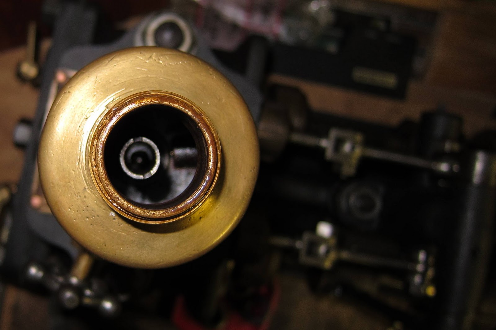
The water cylinder piston rings are made of a fibrous non-metallic material. (click here for more detail). They survived steam ingress the previous time and seemingly this time also as the pump worked well when tested with compressed air.

Wednesday, 27 February 2019

Wear & Tear (2)

After three years of reliable service, Sentinel 7109's cab boiler feed pump decided it was going to play games and started spitting steam out of the steam cylinder end cover joint.

This early photo shows the light green layer between cylinders and the end cover.
June 2011 photo long before putting the pump to work
The material I used for the joint was Klinger's Klingersil C-4400. I'd bought this in 2010. Its spec shows that it can withstand about 23bar pressure at 230degC. All seemed satisfactory as water boils at approximately 230degC when at 19bar pressure.

The next photo shows the effect of three years' use (and possibly the recent heavy frost?).
Comprehensive disintegration of the joint material
There are splits in many places which makes me wonder if there may have been some frost involved but that is speculation.

In retrospect, what is more to the point is that, while the spec shows the joint material is good for 230 degC and 19bar, the steam supply to the pump has passed through the superheater and is likely to be somewhat hotter than the figure I had originally assumed. I'm thus rather surprised it had lasted as this long!

Later in the restoration process, for all steam joints, I'd switched to a higher spec joint material, namely Klinger's Kingergraphite PSM/AS. More details here.

So that's what will be used for the repair.

I can say I now have more (hard-earned) experience!

Saturday, 23 February 2019

Frost Damage February 2019.

Sentinel 7109 was surprised by a sudden frost in early February 2019 and suffered some damage to the pipework feeding the cab's boiler feed pump.

In June 2013, I wrote extensively about the construction of an elaborate plug valve with a hidden secret. It was originally fitted in 1928 so was a historical gem.
Plug valve in water feed line.
However, after the frost, I found it looking rather sorry for itself.
Split top bit
On taking it apart, I realised that it was beyond repair as the internal plug itself had split into two pieces.
Split plug
It's a shame to lose an original part in this way but it was also an opportunity. I suspect the 1928 construction had perhaps been done in a hurry; Joyce was a prototype after all. Where the pipe came from the tank to the 'T' piece, a strainer was hidden across the top of the 'T'. The valve was downstream of the strainer.
There was a disadvantage with this in that to clear the strainer by removing the plug from the end of the 'T', the tank had to be emptied to avoid a personal irrigation. So the valve should have been upstream of the strainer!

I've resorted to modern parts to rebuild the valve and strainer with the disadvantage removed.
Ball valve and 'Y' strainer
The pressure on the ball valve is only the head of the water in the tank, about 6 feet max., so there are minimal requirements for it. The 'Y' strainer is now downstream of the valve and the strainer's cap (pointing downwards) can also be used to drain the water pipe for frost precautions as well as cleaning the strainer. With any luck, the new strainer will be less restrictive than the old one so the water pump should be more efficient.

I'll tidy up the appearance in due course [as below].
With a lick of paint...
...And some frost protection where the pipe can't be drained

Friday, 14 August 2015

In-Cab Boiler Feed Pump Drain Cocks

Having fitted Sentinel 7109's cab boiler feed pump some time ago, there was still some pipework to be completed. I'd constructed the feed from the water tank and the steam exhaust but there was more left to do (and still is!). This article deals with the drain cocks.
There are four drain cocks, one at each end of each of the twin steam cylinders, as in the photo on the right. However, in their original form, they were a mess waiting to happen as they would spew oil and water out on to the cab's ledge.
I decided that they needed drain pipes so that the outflow could end up somewhere more sensible.
3/16" Copper pipe is readily available for automotive brake systems. In preparation, I brazed compatible fittings on to the drain cocks as shown.
The Copper pipe is easy to bend by hand and the final result looks quite elegant.

The four pipes are taken through holes in the ledge and secured to the steam exhaust pipe with tie-wraps. (Let's hope they stand the heat!).
Finally the outlets are strapped to and just above the steam exhaust outlet. There is a thread on the end in case the exhaust needs to be extended later.

Wednesday, 19 June 2013

Hidden Secret

Sometimes the simplest looking items turn out to be more complicated than expected. The off-side water feed valve is one of these.
WS BFP Water Feed Valve
And the same but closer (restored)
It's a 'Plug' valve with a tapered plug and rectangular slot. The plug is held down into the valve body by a screw-down gland plate. These are fairly simple ideas; however, the valve body and its spindle have a hidden secret.
The 'Plug' (Spindle)
Valve body
On the surface, it's easy to see the rectangular slot in the plug which either allows water through or blocks the flow depending on which way it is set.

There is a slot around the top of the plug taper with a pair of holes diametrically opposite each other. So what are they for?

On the top of the spindle is also a hex headed screw. So what's that for?
Hex head screw
Initially, the hex head was well jammed-in with old paint and immovable. With a split-pin hole across the hex head, it looked as if it might have had a purpose at one time. I dug the paint out and managed to free the screw and its purpose began to become clear.

On removing the hex head screw, I could see another screw inside the spindle hole so I removed that too.
Hex head and internal screws
At the bottom of the hole in the spindle is a chamber with the pair of holes leading off to the slot around the top of the plug.

The internal screw is more subtle than I'd initially imagined.
Internal 'screw'
In fact, it is hollow and contains a ball bearing retained by a loop of wire. With a pair of slots at the lower end, the ball acts as a non-return valve.

With the screw in place at the bottom of the spindle hole, grease is loaded into the hole above (best done with a grease gun). The hex head screw is then screwed in to push the grease through the valve and out through the holes to the slot around the top of the plug.

The valve body design works with the plug to distribute grease to all the places it is needed.
Inside the valve body
Looking down into the body, there is a cut-out in the wall which coincides with the slot around the top of the plug. There is also another cut-out at the bottom of the body (the plug-hole?). There are also identical cut-outs opposite the ones visible in the photo. The cut-outs also coincide with four slots down the plug surface.
One of the four plug slots - Note the dark patches at each end of the slot
which match the top and bottom body cut-outs
The grease can thus be forced down into the slot around the plug, through the upper body cut-out, down the slots and finally into the lower cut-outs and the bottom of the valve body. The whole valve can thus be greased in situ whilst doing its job immersed in water. Clever!

A few notes:

Grease can be forced in with the valve spindle in any position. The cut-outs will prevent grease ending up in the water space.

The valve is open when the top looks like this:
Valve Open
The valve is closed when the top looks like this:
Valve Closed
The slot through the plug is in line with the 'pips' on top of the spindle.
Slot lines up with the 'pips'
Not a lot of people know all that!

Friday, 14 June 2013

Recreating an old Photo

I've had this photo for some time and have used it to examine small details of the cab and the Boiler Feed Pump peering from the cab side window.
1933 (Photo - Tony Thomas collection)
Here it is again but this time in June 2013. It was difficult to get the same angle but it's not far off (and I really should have hidden the display panel and put the covers on!).
2013
I've used this cropped-from-the-top photo before to show the pump itself.
1933 BFP Close-up
Send me a comment if you can identify the BFP type shown above. Out of curiosity I'd be interested to know the type (but am unlikely to try to find one - a task lodged firmly in the too difficult pile!).

Here's the new BFP in place. A Worthington Simpson type was specified for a later Sentinel double-engined loco so that's what it will have to be.
2013 BFP Close-up

Friday, 24 May 2013

Displacement Lubricator No 2

Until recently, I'd been searching for an additional Displacement lubricator to ensure a good oil supply to the steam brake cylinder. The one I already had was earmarked for the Worthington-Simpson Boiler Feed Pump.

As luck would have it, a Cornishman was selling the Worthington-Simpson pump off his traction engine on Ebay. Whilst I didn't need the pump, I noticed in one of the pictures that it had a suitable displacement lubricator on top of it. I enquired as to whether the seller was willing to sell the lubricator on its own and, to cut a long story short, I now have it. (This lubricator, being of the type normally used for a WS pump, will be used for that purpose; the previous one can now be redeployed for steam brake oiling).

When complete, the lubricator is almost identical to the one in the photo below.
Colin Evans's Displacement Lubricator
At first I assumed that there was not much that could be wrong with one of these devices. However, on removing the old viscous oil from it for examination, the central tube was flapping about loosely and obviously not able to perform its function properly. (I've already done a description of how one of these works part way down in 'Why you need a pointy hat' some time ago).

The various bits and pieces are shown below:
Lubricator Internals
Closer examination of the small curved tube shows that its thread has worn over time and, unless screwed in tight, would flap about without making the necessary seal with the valve box.
Tube with its threaded hole in the valve box
Worn thread
Threaded hole to the right in the valve box (or whatever it should be called!)
I cleaned up the tube and thread and screwed them together tightly using Heldite jointing compound to keep them in place.
Reassembled curved tube
So now it should work properly (when reassembled!).

One mystery remains with this lubricator. Most displacement lubricators seem to have a valve for draining condensate to the outside world. This one's drain valve releases the condensate back into the steam and oil connection.
The point of the valve seat is to the right of the bottom of the inlet/outlet hole shown
(same for both valves)
So how does the water get out if there is pressure below? Is it only possible to empty when the system is cold? Or do you just use the drain valve and hope?

Comments welcome!

Wednesday, 16 May 2012

Straining the Rubbish

An earlier article has described Sentinel 7109's boiler feed pumps including the cab-mounted one on the right hand side.
Original Cab-mounted Boiler Feed Pump
The pump has to draw water from the water tank via pipework and a coarse strainer situated in a right-angled fitting and isolating valve housing just in front of the cab.
Strainer and Valve Housing by Water Tank
The picture below was taken just after Sentinel 7109 arrived at Midsomer Norton Station in December 2004. It shows how scale and rubbish accumulate at the bottom of the tank. The pipe at the bottom of the picture is the take-off for the cab feed pump. It does not suck directly from the tank bottom and so not too much detritus should be drawn. However, to be safe rather than sorry, the strainer is included. (Another in-line strainer may also be added at the pump inlet).
Bottom of the Water Tank
Since the above picture was taken, much of the scale and rubbish have been removed using a domestic vacuum cleaner (honest!) with a long hose to reach in from the top. Some chemical de-scaling may also be necessary in the future depending on how 7109 reacts to water treatment. An awful lot of Kilrock-K is needed for this type of kettle!
Coarse Strainer Housing
The strainer housing is shown above. When it was first opened, a rather distorted, vaguely cylindrical-shaped, perforated, oxidised, copper thing came out. On trying to reform it into shape, it was obviously going to break and eventually it did.

However, since it was already broken, there was no harm in at least trying to fix it.
I heated the parts to red heat and quenched them in cold water to anneal (soften) them. Then I did the reshaping using a rubber mallet, a 4lb hammer as behind support and a broom handle about the right internal diameter.

I then silver soldered the pieces together as in the picture below.
Repaired Coarse Water Strainer
Hopefully I haven't blocked too many of the strainer holes and it may work better in some orientations than others. However, I think we have a strainer capable of going back into service again!

Thursday, 13 October 2011

Why you need a Pointy Hat

As delivered, this elegant, Penberthy, displacement lubricator will flood the cab-mounted Worthington Simpson Boiler Feed Pump's (WS BFP's) steam chest every time it's topped up. Not good!
Looks good but hides a flaw
Let's see why.
Mounted on top of the WS BFP's Steam chest
The lubricator relies on being mounted vertically with steam oil filled to the top of a centrally located, internal tube.
Main pot removed to show the internal tube
In operation, some steam from the steam chest below is pushed up into the air gap at the top of the main pot where it condenses into water.

Being heavier than oil, the water sinks to the bottom and raises the level of the oil. The oil then spills over into the internal tube and back down into the steam chest below. So this is how the steam oil gets into the steam chest at the same pressure as the steam.

How does the oil get into the main pot? Well, you take off the filler cap and pour it in or so you expect until you actually have a look inside.

The top of the tube is open!
The tube has nothing to prevent oil being poured straight down it into the steam chest. Whilst this probably would not do any great damage, the steam chest would certainly get more oil than required!

I've concluded that there must be a missing part which blocks the hole but still allows the oil to spill over into the tube as intended.


I spent a lot of time figuring out how this part could block yet not block the tube top. Eventually I came up with a sort of castellated pointy hat thing!

Castellated, pointy, hat thing drilled from below to meet six holes and...
...which can sit on top of the tube like this
Now when you look in the top of the pot, it's like this:
Pointy hat top
So pouring oil into the filler will now put it into the pot and not straight into the steam chest!

I wonder if it will still work and what was there originally?
Related Posts Plugin for WordPress, Blogger...