Showing posts with label Pipework. Show all posts

Sunday, 19 March 2023

"I'm Still Here"

After some considerable time without any blog posts, I'm hoping to do some catching up.

My original intention was to record the restoration activities of Joyce so that I would be able to refer back later - it's easier and quicker than actually dismantling an assembly to recall what I did years before. For me, it has been useful on many occasions; I hope it has been helpful to others too.

Of course, the restoration finished in earnest in 2016 when Joyce began pulling passengers. I didn't want to just show pictures of Joyce in action as many others have done that better than me (it's difficult to take good photos from the driver's cab!).

Joyce has been pretty reliable for a steam locomotive but she's kept me on my toes to achieve that. Having J R Goold Steam Ltd close-by has been a godsend for rapid repairs and I am very grateful for their amazing support in times of need.

There have, however, been a few little problemettes...

Here was an unwelcome sight one Sunday morning in May 2021 while getting ready for passenger train duties.
Tell-tale Jet of steam
This was a pin-hole in the main steam pipe feeding Joyce's rear engine. Needless to say, she didn't run that day.
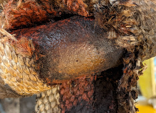
Pin-Hole
I contacted my Goold support team and a new pipe was made then lagged and fitted by me in about 8 days.
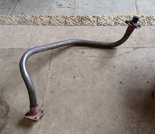
New Pipe
The new pipe fitted perfectly. Godsend is the right word.
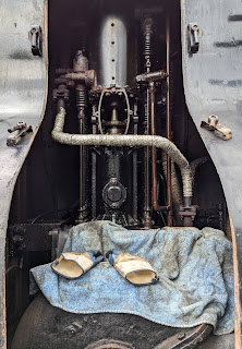
Ready to go again

Saturday, 23 February 2019

Frost Damage February 2019.

Sentinel 7109 was surprised by a sudden frost in early February 2019 and suffered some damage to the pipework feeding the cab's boiler feed pump.

In June 2013, I wrote extensively about the construction of an elaborate plug valve with a hidden secret. It was originally fitted in 1928 so was a historical gem.
Plug valve in water feed line.
However, after the frost, I found it looking rather sorry for itself.
Split top bit
On taking it apart, I realised that it was beyond repair as the internal plug itself had split into two pieces.
Split plug
It's a shame to lose an original part in this way but it was also an opportunity. I suspect the 1928 construction had perhaps been done in a hurry; Joyce was a prototype after all. Where the pipe came from the tank to the 'T' piece, a strainer was hidden across the top of the 'T'. The valve was downstream of the strainer.
There was a disadvantage with this in that to clear the strainer by removing the plug from the end of the 'T', the tank had to be emptied to avoid a personal irrigation. So the valve should have been upstream of the strainer!

I've resorted to modern parts to rebuild the valve and strainer with the disadvantage removed.
Ball valve and 'Y' strainer
The pressure on the ball valve is only the head of the water in the tank, about 6 feet max., so there are minimal requirements for it. The 'Y' strainer is now downstream of the valve and the strainer's cap (pointing downwards) can also be used to drain the water pipe for frost precautions as well as cleaning the strainer. With any luck, the new strainer will be less restrictive than the old one so the water pump should be more efficient.

I'll tidy up the appearance in due course [as below].
With a lick of paint...
...And some frost protection where the pipe can't be drained

Wednesday, 13 July 2016

Braided Flexible Hose

Leading up to the March 6th 2016 deadline for the 50th anniversary of the closure of the Somerset and Dorset Railway, I was faced with many outstanding jobs to get Sentinel 7109 in steam for the event. I knew I had eleven or so pipe runs to fabricate for carrying superheated or saturated steam as well as water and oil, all at 275psi boiler pressure.

While I could have kitted myself out with copper pipe tooling, it was going to make the job too lengthy to meet the deadline. I’d been recommended stainless steel braided hose as a possibility and after some internet searching found Guyson’s Kaptech hosing. (www.Guyson.co.uk).
Stainless Steel Braided Hose
After some discussion with Guyson’s technical department, I found that they could make to order in a fairly short time the hoses I wanted with the right lengths and connections to suit the existing fittings on 7109. In addition, each pipe run had to suit the pressure and temperature ratings required.

All hoses would have to withstand 275psi. Superheated steam hose would have to withstand the pressure at up to 380DegC, the max superheated temperature measured by Sentinel in their test department. Saturated steam would be up to 230DegC. Cylinder oil from the mechanical lubricator and water from the feed pump would be at relatively cool temperatures.

I chose all the steam hose to be 3/8” Nominal Bore (NB) annularly corrugated 321 stainless steel lined; the water feed hose to be 1” NB PTFE lined and the cylinder oil feed to be ¼” NB PTFE lined. All would need only the single outer braiding layer.

The maximum pressure and other ratings for the annularly corrugated hose are in the following table (from Guyson):
Stainless Steel Hose Ratings
Thus my 3/8” NB hose with single braiding would take 100 bar (~1500psi) at room temperature.

The pressure derating table for temperature is below.
Pressure derating for temperature
At 380DegC, the pressure rating would still be around 74% of 100bar, i.e. ~1100psi. This is a very high specification indeed with plenty in hand for a Sentinel. The PTFE lined hose was not so highly specified for temperature but not a weakling by any means.
PTFE Lining rating
The ¼” NB cylinder oil hose would thus handle 240 bar (~3600psi) and the 1” water feed hose 55 bar (~825psi).

In order to purchase the various hoses, I prepared a spreadsheet table with the following information (two examples shown).
Information to specify a hose
I sent this to Guyson who responded with their own internal manufacturing version for me to check. After a few iterations, we settled on a final spec for manufacture and I placed the order. It all arrived in a few weeks.

The following photos show how the hose was used.
3/8" hose as part of the blower supply
These short sections of hose were later connected to a ‘T’ piece leading back to the blower valve. Despite ordering a 6” length, I found that the flexible part was much shorter than 6” due to the end fittings. Thus the curve radius had to be tighter than I wanted and the final appearance not ideal.

This was not the only time I found the fitting length getting in the way of a tight bend.
3/8” hose from the feed pump regulating valve
The connection to the feed pump valve required a hex nipple to fit a female hose end fitting. These fittings are a hydraulic type but similar in many ways to the original for copper pipe. Hydraulic fittings generally use a cone seat rather than flat face with copper washer to seal so I had to use a lathe to convert the nipple cone into a flat face.
3/8” elbow fitting at feed pump
Elbow fittings can make life simpler but need to be thought out carefully before ordering. Again I found I needed a parallel thread hex nipple and copper washer to fit the pump. Being superheated steam, I was not happy with a tapered thread fitting here.
3/8” in and out feeds for steam brake valve
The pressure capability of the flexible hose is provided by the outer braiding with an annularly corrugated inside tube providing the flexibility. As such, the failure of flexible hose is down to abrasion of the braiding. Where the hose had to pass through a hole and could chafe the sides, I wrapped silicone fire sleeve (silicone coated glass fibre) around as protection. While the hose can move about, it is now well protected from chafing. For hose such as the steam brake supply, pressure is applied and released. The hose hardly moves with the changes in pressure.
3/8” whistle and pressure gauge feeds, the latter incorporates the loop
For the boiler pressure gauge feed, I was able to wrap the hose into a loop to keep the steam out of the gauge.

The whistle has been supplied by flexible hose too; however, this may be the cause of the whistle seeming to be choked with condensation unless used frequently. Despite using various sizes of orifice to regulate the steam flow rate to the whistle, it always has to ‘clear its throat’ before coming on tune. I suspect that condensation accumulates in the inner tube corrugations with the hose not being lagged so further investigation is required. Suggestions?
1” PTFE water feed hose from feed pump to single check valve
With the pulsing of the Worthington Simpson pump, the 1” PTFE hose moves about quite a bit. I’d be better off with an anti-shock bulb at the pump end to smooth out the pulses.
¼” PTFE hose, 11 feet long section in the cylinder oil feed
The cylinder oil feed takes a tortuous route around the pipe work underneath and then circumvents the boiler. There was an eleven feet gap in the original pipe to the regulator assembly. The ¼” PTFE hose filled this gap very elegantly. I used ‘nutserts’ to attach the hose to the boiler cladding.

In summary, I would say that flexible hose is an elegant alternative to copper tubing; however, there are various factors to be borne in mind.

1. It lacks the authentic appeal of copper piping.
2. It can be ordered ready to fit (provided you get your specification right – not trivial and prone to mistakes).
3. The hose is flexible but cannot twist and can thus be awkward to fit at times.
4. The length of the fittings may get in the way. Consider an elbow fitting if a right angle exit is needed.
5. For short hose lengths, take great care about the minimum bend radius specification.
6. For joins in the flexible hose such as a ‘T’ joint, the standard hydraulic cone fitting can be retained. They work very well between themselves but won’t mate with the original copper washer fittings.
7. Any type and size of fitting can be ordered for any diameter of hose. This could give some pretty bizarre assemblies but technically it is possible.
8. Lengths have to be thought out carefully. It is tempting to think that a bit extra will make life easier. In fact the extra can get in the way and it’s ‘return to factory’ if it needs shortening.
9. Chafing must be prevented. An annual inspection of the braiding should be performed – no different to any other pressure tubing.
10. If vibration is likely, make sure the hose is secured in place as with any other tubing.
11. Stainless steel fittings are the norm. There is little saving to be had with none stainless types.
12. Copper washers are needed for flat face parallel thread fittings (same as with copper tubing fittings). I also used Steamseal to make sure.
13. The PTFE inner lining can kink if twisted.

The entire set of flexible hoses was in the region of £1000. Would I recommend this approach? Certainly!

Monday, 4 January 2016

Implementing 'A Little Arithmetic'

In a recent Sentinel 7109 article, I did some 'arithmetic' to enable a new boiler blow-down valve to be fitted. The result was this elongated heavy duty hex nipple pipe fitting made by Justin Goold.
Elongated Hex Nipple
The photo below shows that it has provided the solution required and is a good, strong fit to support the substantial high-spec blow-down valve.
The Valve is firmly screwed into the wash-out plug-hole
Another view shows valve handle in its closed position. An extension handle like those used to turn-off your household water supply in the street will be useful here.
The handle is reached from the off-side
preferably with a long reach extension
Down-stream of the valve, the pipe fittings are galvanised malleable iron as there is no longer the boiler pressure to withstand.
Not a good place to be when the valve is opened!
Another hole in the boiler plugged!

Important Note: The boiler has four washout plug holes at 90 degree intervals. For washout purposes, only the three actual plugs should be used. Only under extreme circumstances should this valve and its hex fitting be removed. The result would be that it will not be able to be tight and in the correct orientation after refitting due to wear on the threads when it was tightened up previously. Thus, it has to be a fit once and leave well alone item.

Monday, 21 December 2015

Boiler Feed Plumbing

On the shortest day of December 2015, Sentinel 7109 received another milestone of reassembly.
Twin Check Valve unit with single check valve to the right
The pipework connecting the two engine-mounted water pumps to the boiler's twin check valve was completed. The single check valve used with the cab mounted pump is in the shade to the right. (A check valve allows the water to only flow in one direction. Hence, water can be put into the boiler without it coming straight out again!).

The twin valve takes water from each pump but allows it to be recirculated to the water tank if not needed by operating the red handles. This is important because the engine pumps are always working when the loco is moving.

I'm really pleased with this pipework as it is original but was not fitted when the loco arrived at Midsomer Norton in 2004.

Wednesday, 25 November 2015

A Little Arithmetic

In one of my previous articles, I showed the boiler having a leg to stand on. I remarked that the 'leg' would be made from red band steel pipe when complete. However, when I considered this further, it would have meant a fairly long section of pipe on the end of which would be the blow-down valve itself.

I concluded that the torque required to operate the valve repeatedly could potentially loosen the pipe where it screwed into the boiler. In the worst case, it could damage the boiler's thread.

I decided that a heavy duty steel nipple would do the job well and be much stronger as well as being shorter. However, when I came to try such a nipple, it went up to the end of its tapered thread in the boiler's hole. Thus, I was not confident it could seal properly.

The Heritage Railway Association (HRA) have published a document on boiler washout plugs. They are very concerned that the male and female threads for boiler plugs should be compatible and not a mixture of seemingly well fitting threads. Whilst this blow down valve is clearly not a boiler plug, it does fit into a boiler plug hole with a tapered thread and I have ensured that the threads will be the correct fit.

Sentinel used 1.25" tapered BSP threads for their boiler plugs although they made the taper longer to allow for wear due to regular removal and replacement. Now for the arithmetic:
Plug + Nipple = Plug-nipple!
I asked Justin Goold to make me a nipple with the boiler plug thread at one end with the normal BSPT at the other.

I have yet to check the fit but I'm sure there will not be a problem initially. I say initially because if wear does take place, the handle of the blow down valve will rotate with each tightening and not so easy to operate. Some care will be required.

Monday, 23 November 2015

Cylinder Oil Reaches Regulator

On a Sentinel locomotive such as 7109, Steam or Cylinder oil is injected into the superheated steam supply as a means of lubricating the engines' cylinders.

As the steam supply is at boiler pressure, the oil needs to be injected under pressure and that pressure is generated by a mechanical lubricator. I've described much of its configuration in an earlier article.

Part of the pipe leading from the Mechanical Lubricator to the regulator was missing from 7109 and I decided that it would be simplest to replace it and fill the gap using PTFE lined flexible high-pressure hosing with integral fittings.

Initial efforts failed to pump any oil into the new pipe section so I had a think and came up with a Heath Robinson construction to cure the problem. It actually follows from an idea described in the Delvac Mechanical Lubricator's manual (courtesy of the National Library of Australia). The intention is to use a lever to operate an individual pump as shown below.
Unsophisticated!
It operates like this (Also on YouTube):

The end result is shown below:
Oil Dribbles from the bleed valve outlet
The braided flexible hose is shown fixed below the bleed, check and oil regulation valve assembly.

Monday, 17 August 2015

Safety Valves (2)

My last look at Sentinel 7109's safety valves was about two years ago. Then I'd initially mounted them on the first version of a manifold constructed from heavy duty steel pipe fittings.
First attempt
All seemed good at the time but a number of factors began to come to light that meant some changes had to be made.

  1. I wasn't sure that the metal of the threaded nipples connecting the steel fittings was strong enough and may have been made from 'Blue band' rather than 'Red band' grade pipe. (Red band pipe has a thicker wall and is rated suitably for the Sentinel boiler's wet steam conditions. Blue band is not good enough).
    I replaced the connecting nipples with heavy duty hex nipples which are much stronger.


  2. I was concerned that when I removed and refitted the safety valves for the boiler's next and any subsequent hydraulic tests, the thread would not make as tight a joint as the first time. They would also need to be removed to fit the boiler top cover.
    I inserted a 3000 psi rated union and mating nipple between the manifold and each safety valve body. The union is designed to be undone and also enables the safety valve to be correctly orientated so its exhaust pipe would align with its hole in the cab roof when refitted.
    This does make the assembly taller but practical!

  3. I had assumed that I could obtain a steam supply for the vacuum brakes, the whistle and the pressure gauge from the four-way manifold used to feed the superheater. However, with all the other pipework in place, it was too inaccessible particularly to reach an isolating valve in that location.
    I thus decided that the safety valve manifold would have to include the steam supplies for the vacuum, whistle and pressure gauge.

  4. At least one of the safety valve outlet pipes would have to pass through cab roof support girders. Not good!
Here's the result. Hex nipples hold it all together. The 3000 psi unions sit below the safety valve housings. The two 'L' shaped fittings are now 'T' shaped so the extra outlets can be taken from each of the new 'arms'. The vacuum supply is downwards from the left 'T' and the whistle and gauge supply horizontally from the right 'T' to an isolating valve.
The exhaust outlets now straddle the roof support girder!
Not cricket wickets!
There's more to do to prevent the pipes rattling in the cab roof holes and to ensure it all lines up if taken apart and reassembled.

Friday, 14 August 2015

In-Cab Boiler Feed Pump Drain Cocks

Having fitted Sentinel 7109's cab boiler feed pump some time ago, there was still some pipework to be completed. I'd constructed the feed from the water tank and the steam exhaust but there was more left to do (and still is!). This article deals with the drain cocks.
There are four drain cocks, one at each end of each of the twin steam cylinders, as in the photo on the right. However, in their original form, they were a mess waiting to happen as they would spew oil and water out on to the cab's ledge.
I decided that they needed drain pipes so that the outflow could end up somewhere more sensible.
3/16" Copper pipe is readily available for automotive brake systems. In preparation, I brazed compatible fittings on to the drain cocks as shown.
The Copper pipe is easy to bend by hand and the final result looks quite elegant.

The four pipes are taken through holes in the ledge and secured to the steam exhaust pipe with tie-wraps. (Let's hope they stand the heat!).
Finally the outlets are strapped to and just above the steam exhaust outlet. There is a thread on the end in case the exhaust needs to be extended later.

Thursday, 13 August 2015

Main Steam Pipe Release Valve Outlet

When Sentinel 7109's regulator is closed, it blocks the steam supply pipe to the engines. With a four to one reduction ratio between the engine speed and the axle speed, this will provide what's called 'Engine Braking' (Big time!).

To prevent things stopping too abruptly, a release valve is provided that opens the main steam pipe to atmosphere when the regulator is moved back to the right beyond the closed position.
Release Valve (at the bottom)
On the regulator handle is a 'lump' containing a spring and a ball. On the housing is a hole which marks the regulator closed position. When the regulator is closed, the ball notches into the hole to indicate closure. The regulator handle then has to be pulled back beyond the closed position to open the release valve.

I had to shape a 1/2" pipe to fit around the main steam pipe and through the original hole in the footplate.

There were two challenges:
(1) Having used a union at the top end of the pipe, I found the nut used to tighten the union fouled the nuts holding the main steam pipe end fitting in place. I thus had to add a short extension to drop the union out of the way.
Elegantly shaped Release Valve Outlet Pipe
(2) The hole in the footplate was under the boiler cladding such that the lower pipe end would not fit through the hole. I thus had to cut the pipe, add a coupling and feed the lower end of the pipe up from underneath. I cut a tapered thread on the top section of pipe and screwed it into the coupling very tightly. I cut a parallel thread on the pipe from below such that it would be the section that came out of the coupling if it ever needed to be removed in future. (The coupling itself will not fit through the hole).
Lower section of pipe below the footplate
'The End'
I've put a round-edged coupling on the end of the pipe to prevent me from gouging a lump out of my head whilst passing underneath!

Sunday, 31 May 2015

Vacuum Braking (13) Implementation (7)

Sunday May 31st 2015 has been mainly about the vacuum braking pipework but not entirely.

In my last article, I'd begun to assemble the vacuum ejector pipework. Now I've pretty well completed it as shown below.
Steam supply linked to the Ejector
The main work was either side of the blue pressure reducing valve (PRV).
PRV, condensate drain valve and unions at either end
Both upright ends had to be parallel in order to mate with the union counter parts. (If I've not said before, unions allow the pipework to be taken apart and also enable rotation).

In the above photo, there are unions at each end of the pipe but, in the first photo, the upright larger diameter pipe also has unions allowing it to rotate. In this way, the distance between the PRV and ejector has been made non-critical and hence much easier to assemble.

The next task was to add some support for the vacuum hoses. Previously the 'Swan necks' on the buffer beams had left only a short length of pipe to attach the hose. I'd felt that some extra length was needed in case the hose could lever itself off.
Lengthened 'Swan neck'
The extension was made from a straight pipe coupling and spare male threaded pipe. The threads were sealed with Heldite.
Comparison with usual hose attachment
The extension is still a little short compared to a normal hose fixing. However, if there is a tendency for hoses to come adrift, the extension can be extended further to fix the problem!

Some time ago, I decided that I wanted to take the steam supply for the whistle and pressure gauge from the safety valve assembly instead of the two outlets at the ends of the four-way manifold which feeds the superheater. It saves one expensive isolating valve and make the valve actually reachable by hand!

I thus had to block the manifold outlets. I used a heavy duty steel cap for one end and a coupling and plug for the other (I had the cap already and I couldn't get another off the shelf).

Since these items were round, I was advised that a Stillson wrench was the best way to tighten them despite the likelihood of some surface damage in the process.
Screwing it up!
To ensure a good seal, I made a pair of thick annealed copper washers and applied a liberal amount of Steamseal to make sure.
The cap fits
The Plug fits!
Now to make a hole in the roof for the ejector exhaust.
Related Posts Plugin for WordPress, Blogger...