Showing posts with label Chains. Show all posts

Wednesday, 7 August 2019

Improved Oiling for the inter-axle Chain

Whilst I've written extensively about Sentinel 7109's front drive chains, I've said very little about the chain which links the two axles. It does the job more conventionally performed by connecting rods. The chain was in place when Joyce arrived in 2004 and I've largely just left it to get on with its job.
Highlighted original oil pot and down-pipe with wipe-rag
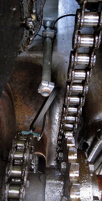
Oiling the chain was originally done by gravity. A pot fed oil down a tube to the chain via a rag which wiped oil on the links as they moved past.

The oil pot was another example from Joyce's missing items portfolio so I had to construct a new one. I used the end section of a small argon gas cylinder and added a valve to turn the flow on and off.

These items are hidden in the photo below beneath an upturned metal cover (OK, it's a bean can but it was a perfect fit!). The down-pipe is original but the new rag was a hem extracted from an old pair of jeans.
Gravity-fed oil feed
In so far as it went, it could do the job just about adequately but I was forever either forgetting to turn it on before moving off or leaving it on when stopped so one link got deluged and the rest left dry. (Perhaps the original pot used a wick?). What was really needed was a similar system to the front drive chains such that oil would only be provided when moving.
Being driven by the engines, the mechanical lubricator was an ideal candidate but its four pump barrels were already allocated.
Mechanical Lubricator (before restoration)
In the above view, the right hand pump feeds the near-side drive gear bearing and the next one feeds the off-side drive gear bearing. The third from right feeds the steam supply and the left hand one feeds the front chains via a pair of drip trays.
Drip trays and drip feed tubes
Initially I thought that the mechanical lubricator was out of bounds but experience showed that a good supply of oil was already being fed through the drive gear bearings into the drip trays without any additional oil required from a dedicated pump. Thus the left-most pump was effectively a spare.

In the back of my mind has always been the thought that 7109 was a prototype and thus some parts/methods of operation were possibly experimental and not well tried and tested; they could thus be improved.
Oil from the gear bearings into the drip tray
I set out to construct a feed from the mechanical lubricator to the inter-axle chain. My plan was to suspend a three-drip device above the chain and connect it by a pipe to the lubricator.

A number of parts needed to be made:

1. An adaptor to connect a pipe to the lubricator pump.
2. The pipe itself (I chose to cheat and use rubber fuel hose).
3. The three-drip device.
4. Rigid support for the feeder so it wouldn't shake it all about.

The adaptor seemed an easy task: it would be needing BSP threads obviously? No it wouldn't! To cut a long story short, it needed a rare British Standard Cycle thread as used on push-bikes and motor bikes. The thread was actually 3/4" 20tpi and taps and dies were surprisingly easy to obtain (Ebay).
The rubber hose adaptor rightmost
The adaptor consists of a coupling with a female 3/4" BSC thread end to end and a plug screwed into the top. The plug is tapped for a standard 1/8" BSP hose adaptor. The coupling is screwed on to the pump first. The plug seals against the top of the pump with a fibre washer. Heldite was used to seal the hose adaptor.
Three-drip device
I wanted to be able to set the three-drip device so that it would dribble on the left and right links of the chain as well as centrally on the rollers. Thus it would be required to be able to be rotated to get the drippers the right distance apart and in the right place.

Any resemblance in the body of the device to a Lidl compressed-air adaptor are purely coincidence of course (but it saved a lot of work for very little cost!).
The dripper attached to an angle-iron support
The complete dripper support
I made the rigid support using a pair of Stauff clamps to fix a vertical piece of 1.25" steel pipe (same as used for the vacuum braking pipework) to the front of the water tank inside the engine compartment.
Pipe clamped to the water tank
I then attached the angle iron support bracket to the pipe with another Stauff clamp.
Viewed from underneath
Stauff clamps grip the pipe very tightly and the dripper is held very robustly in place.
Not an easy photo so take (apologies for low quality)
The rubber pipe is supported in a fairly low-tech manner.
Rubber pipe routing
After a lengthy non-trivial design and installation task, I tried it out on a passenger operations day. It certainly works and there is now no shortage of oil for the drive and inter-axle chains and one less job to do when preparing to steam. There is still a good deal of fiddling about to do yet to get the flow rates right, not helped by the newly sorted central heating for the mechanical lubricator. The oil is now warmer and thinner as a result and the pumps provide more oil than before.

One question I don't have the answer to is how much oil does a chain need? I haven't oiled my mountain bike's chain for years and it is still happy; however, these chains work a little harder than my bike's so sufficient will be enough.

I'm also hoping to reduce the oil consumption. 7109 uses about 3 pints of cylinder oil a day - that seems a lot to me.

I'll remove the old gravity-feed oiler when all is set up satisfactorily.

Friday, 15 April 2016

Re-Chained Malady

Last time I wrote about fitting the two drive chains, I'd been concerned that one chain seemed much slacker than the other. I counted the number of links on each chain and checked that the corresponding sprockets had the same numbers of teeth. All were present and correct. 

Fellow member of the Sentinel Drivers Club Keith Reynolds visited the Midsomer Norton station open day at the end of February 2016. He explained that chains can stretch and that this was probably the cause. The stretch can be detected by laying the chain on its side and lifting one end. The curvature of the chain indicates the level of wear in the link roller bearings. The greater the curve, the greater the wear.

Although I could not do this while the slack chain was in situ, kicking it showed that it had a lot of sideways play.

So I decided that the best option was to simply replace it with another of the spare chains and take a chance on the result.

I was lucky as can be seen below. The two chains are very similar in tension now and I didn't have to do any axle adjustment.
Nearside chain replaced (the less shiny one)
The two chains are now similarly tensioned.
So a day well spent.


My apologies for the lack of blog material lately. Actually operating 7109 is great fun but without a 30ft selfie stick, it's very difficult for the driver to get any of his own photos!

Tuesday, 16 February 2016

Chained Malady!

Just to complete my last article about enchaining Sentinel 7109, here is the new view beneath the frames looking from the front.
Drive chains in place
It's not clear from this photo that the chain on the right (of the photo) is slacker than the other. Despite very careful setting up of the axles and even more thoroughly checking that the chains were actually the same length, one chain insists on drooping. At present, I don't know the cause of this although I expect they will equalise with running in.

I also previously referred to items called chain 'slippers' and these are in the photo below.
Chain 'Slippers'
Whether these resemble Sentinel's idea of a chain slipper, I don't know; however, they did the job required of them.

Friday, 12 February 2016

Unchained Malady!

The last time I wrote about chains was in January 2012. That was to do with renovations, now it's time to actually fit them to Sentinel 7109.

After some discussion, I concluded that to fit these heavy items safely in an awkward situation was not going to be easy and required the preparation of some special tools to assist. It was going to be quite a complicated process to be able to get the chains into position mid-way between the sprockets and then get the chains over the sprocket teeth so that the two ends could be joined.

The first tool is a trolley to carry the chain under the loco.
Chain trolley
The centre of the chain is placed in the centre of the trolley with each end piled up to allow it to be pulled over its respective sprocket.
Trolley with chain in position
The trolley and chain are then put on a plank to wheel the chain into position. The upright support piece of wood is to prevent the trolley drifting off the plank and on to my lap whilst underneath!
Ready to go under
The next tool is, as Sentinel called it, a chain 'slipper' to allow the chain to be dragged over the sprocket teeth. One is needed for each sprocket.
Chain 'slippers' in place
I made the slippers from Aluminium strip left over from another job. I drilled a hole at each end and put in a bolt and nut to enable a strap to pull the ends together.
Axle sprocket with slipper
For the second slipper, I used two bolts so that a ratchet strap could be used to tighten the slipper with static straps to hold it once tight (I only have two ratchet straps so limited resources!).
Ratchet & static straps on drive sprocket
The chain was then wheeled into place...
Ready to drag chain over slippers
...and dragged over the drive sprocket.
Up...
...and over
The chain was then secured to prevent it from slipping back over.
Secured from slipping back
Then the slipper was pulled out after removing the bolts from one end to allow it to pass under the chain. (It had to be pulled quite hard!).


The same process was then applied to the axle sprocket and the two ends pulled together with a light duty lorry strap.
Ends pulled together from afar...
...and from anear with both slippers removed
At this stage, I came to the conclusion that the light duty ratchet strap was not strong enough to pull the ends together and that a heavier duty type might do the trick.
This photo shows that even that was not going to solve the problem.
So near yet so far!
I had assumed all along that the axles would be in the same position as when the chains were removed. However, clearly that is not the case and the axles and brakes will all have to be adjusted to get the sprockets the right distance apart for the chains to fit with the correct tension (+/- 2" movement mid way between sprockets).

Sunday, 22 January 2012

Chains - Free at last!

After about seven weeks, Sentinel 7109's pair of big-time bicycle chains have finally given in to the lengthy diesel dunking and manipulation with hammers and Stillson wrenches; now all rollers and links are free to move.
Flexible chain links ...
... wound round semi-sprockets
So the work is now complete to ensure there are at least two workable drive chain sets. A deep oiling will be required before use.

Friday, 2 December 2011

Diesel Dunking for the Chains

Here's Sentinel 7109's offering for submerging a celebrity in slime!
Is it a snake?
Eel maybe?
In actual fact, this is the recommended method for reconditioning rusty chains. As of 27th November 2011, two of the huge chains described in an earlier posting are now lying in a nice moisturising bath of diesel and thin oil.

After much searching for a suitable container large enough and strong enough to take a pair of chains, a S&DRHT volunteer, Dave Read, came up with the ideal thing, an agricultural style tank which may have done service in a dairy originally! It's always a good idea to explore other technologies for solutions to your own!

The chains will remain submerged for a couple of months before further examination.

One method of cleaning the chains I was recommended was to set fire to them to dry off the diesel. How ever good an idea it may be, the H&S police would probably have a heart attack at the thought!

Monday, 21 November 2011

The Midsomer Norton Station Bicycle - Big Time!

Midsomer Norton Station visitors have been developing a curioius interest in evidence for the existence of a giant bicycle. I have to admit there certainly is some evidence. Have a look at these photos taken 20th November 2011:
Bicycle Chains?
Nothing in the above to show the size of the chains.
But hang on, 2 7/8 inches wide...
... and a pitch of 2 1/2 inches?
This must be some bike!

OK, not a serious article. These are of course Sentinel 7109's drive chains before cleaning up and freeing. Only 3 are needed but they are just a little larger than for your average bicycle, don't you think?
Related Posts Plugin for WordPress, Blogger...