Monday, 21 December 2015

Boiler Feed Plumbing

On the shortest day of December 2015, Sentinel 7109 received another milestone of reassembly.
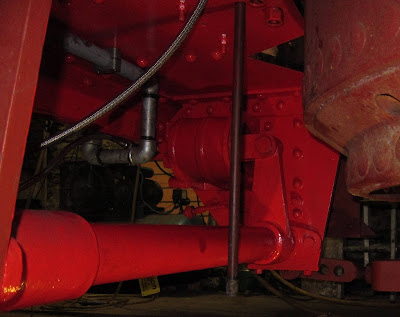
Twin Check Valve unit with single check valve to the right
The pipework connecting the two engine-mounted water pumps to the boiler's twin check valve was completed. The single check valve used with the cab mounted pump is in the shade to the right. (A check valve allows the water to only flow in one direction. Hence, water can be put into the boiler without it coming straight out again!).

The twin valve takes water from each pump but allows it to be recirculated to the water tank if not needed by operating the red handles. This is important because the engine pumps are always working when the loco is moving.

I'm really pleased with this pipework as it is original but was not fitted when the loco arrived at Midsomer Norton in 2004.

Sunday, 13 December 2015

Steam Brake Air Tested

In June 2012, I last wrote about Sentinel 7109's steam brake cylinder. Time passes and I've learnt that restoration is not a rapid activity!

The brake cylinder was reinstalled on Monday 7th December 2015 and here it is in place bolted to the left hand frame member to the rear of the boiler. (Bearing in mind that I can only just lift the cylinder on my own, getting it into place under here was not a straight forward exercise and required a selection of trolleys, levers, bits of railway sleeper and a lot of ingenuity to get it home!).
Brake Off
Spot the difference!
Brake On
To see it in action, here's another of my little video clips (Also on YouTube).

Sounds like heavy breathing!

The testing involved connecting a compressed air supply to the Driver's Brake Valve (DBV) inlet. Movement in the video was controlled using the DBV itself as would be normal practice with a steam supply.
DBV Top Left
The brakes still need to be adjusted but that can't happen until the front drive chains are in place and the axles located for the correct chain tension.

Checking back over the 'blog, I've not been able to find anything on the Driver's Brake Valve itself. I've had the photos since December 2012 but they slipped through the net.

The Driver's Brake Valve has an operating shaft and three connections to it - the steam supply inlet from the boiler; the outlet to the brake cylinder and a drain to atmosphere to release the pressure on the cylinder piston to let the brake off after application.
DBV connections
DBV Operating shaft
The operating shaft is extended across the rear of the cab to allow the brake to be operated from either side.
Dual Controls 1927 Style!
I took the following photo just after taking co-ownership of 7109 in 2010. A few bits & pieces had been removed and examined ('played with'). There was a long journey ahead!
DBV in October 2010
For completeness, here's the Sentinel factory drawing of the DBV. It is a general drawing showing that it could be operated from either end although 7109 did not use it that way.
Sentinel DBV Sectional Drawing
Other locos mounted the DBV in the centre rear of the boiler with handles either side.
DBV in Sentinel 9599 (William Mk1)

Tuesday, 8 December 2015

Remote Control - 1927 Style in 2015

I began this small series three years ago here. With due regard to health and safety, I did not complete the construction as there would have been a trip wire to negotiate at the same time as squeezing into the right front corner of the cab where most of the vacuum braking and safety valve apparatus was being made resident. (I've lost count of the number of times I've had to breathe in very deeply to avoid impaling myself on the safety valves and vacuum gear).

The trip wire is now in place ready for the unwary (probably me on bad day!). There is a lot more to go in this corner and much not obvious in this photo.
Trip wire in place
Below the cab floor, the cable attaches to the exhaust condensate valve. (Also shown here is the new stainless steel braided (High-tech!) mechanical lubricator feed pipe to the regulator steam supply).
Underneath end of the remote control cable
The cable passes through the cab floor by the vacuum pipe.
Through the cab floor (1)
The two water feed pipes from the engine-mounted boiler feed pumps are showing - and still need to be linked to the boiler. The cable looks as if it will rub against the water pipe. Some care will be needed here.
Through the cab floor (2)
From a different angle:
Through the cab floor (3)
Looking at the photos in the earlier article, it brings home just how much has been done over those three years (and that the amount still to do is looking a lot more encouraging!)...

Thursday, 3 December 2015

Shiny!

On Monday 30th November, Eric Miles and George Colbourne took a break from restoring the Fry's Sentinel Loco at the Avon Valley Railway and kindly visited Midsomer Norton bringing with them two brand new Sentinel Maker's plates for 7109.
Bare Metal Sentinel Loco Maker's Plate - Nice!
They have had a slight clean up so far and are ready to have the number punched on the blank rectangle at the bottom right. The background will be painted red as was the Sentinel tradition in 1927. I have yet to discover the exact shade of red required.

Wednesday, 25 November 2015

A Little Arithmetic

In one of my previous articles, I showed the boiler having a leg to stand on. I remarked that the 'leg' would be made from red band steel pipe when complete. However, when I considered this further, it would have meant a fairly long section of pipe on the end of which would be the blow-down valve itself.

I concluded that the torque required to operate the valve repeatedly could potentially loosen the pipe where it screwed into the boiler. In the worst case, it could damage the boiler's thread.

I decided that a heavy duty steel nipple would do the job well and be much stronger as well as being shorter. However, when I came to try such a nipple, it went up to the end of its tapered thread in the boiler's hole. Thus, I was not confident it could seal properly.

The Heritage Railway Association (HRA) have published a document on boiler washout plugs. They are very concerned that the male and female threads for boiler plugs should be compatible and not a mixture of seemingly well fitting threads. Whilst this blow down valve is clearly not a boiler plug, it does fit into a boiler plug hole with a tapered thread and I have ensured that the threads will be the correct fit.

Sentinel used 1.25" tapered BSP threads for their boiler plugs although they made the taper longer to allow for wear due to regular removal and replacement. Now for the arithmetic:
Plug + Nipple = Plug-nipple!
I asked Justin Goold to make me a nipple with the boiler plug thread at one end with the normal BSPT at the other.

I have yet to check the fit but I'm sure there will not be a problem initially. I say initially because if wear does take place, the handle of the blow down valve will rotate with each tightening and not so easy to operate. Some care will be required.

Monday, 23 November 2015

Cylinder Oil Reaches Regulator

On a Sentinel locomotive such as 7109, Steam or Cylinder oil is injected into the superheated steam supply as a means of lubricating the engines' cylinders.

As the steam supply is at boiler pressure, the oil needs to be injected under pressure and that pressure is generated by a mechanical lubricator. I've described much of its configuration in an earlier article.

Part of the pipe leading from the Mechanical Lubricator to the regulator was missing from 7109 and I decided that it would be simplest to replace it and fill the gap using PTFE lined flexible high-pressure hosing with integral fittings.

Initial efforts failed to pump any oil into the new pipe section so I had a think and came up with a Heath Robinson construction to cure the problem. It actually follows from an idea described in the Delvac Mechanical Lubricator's manual (courtesy of the National Library of Australia). The intention is to use a lever to operate an individual pump as shown below.
Unsophisticated!
It operates like this (Also on YouTube):

The end result is shown below:
Oil Dribbles from the bleed valve outlet
The braided flexible hose is shown fixed below the bleed, check and oil regulation valve assembly.

Sunday, 22 November 2015

Chuff Proofing (3)

In Chuff Proofing (2), I showed the 'completed' superheater steady plates for both inlets and outlets. I later realised that one of the screw fixings was loose and would need to be enlarged from 3/8" BSW to M12 and the hole re-tapped for a secure fit.
M12 screw highlighted on plates at the rear
(i.e. nearer the regulator)
Having enlarged the one I knew about, when checking, I found two more loose ones on the plates towards the cab front.
M12 screws highlighted on the plates at the front
(i.e. superheater inlet)
Hopefully these will all be secure in the long term and rattle proof. (I hate rattling noises).

Saturday, 21 November 2015

Vacuum Braking (15) Implementation (8)

Working Under Less Pressure than the boiler, the vacuum brake ejector requires 60 psi to work most efficiently. I began to describe this in an earlier article.

The missing item was a gauge to measure the pressure entering the pressure reducing valve.
Ejector Pressure Gauge Mounting
The gauge is clamped to the upward tube and marked mid-way between 40 and 80 psi.

Steam gauges are always fed by a tube with a loop or dip before the gauge. It collects condensation and prevents the steam entering the gauge and melting the soft-soldered delicate parts inside.

Wednesday, 30 September 2015

Working Under Pressure?

I've been fitting the boiler pressure gauge lately. It's red lined at 275psi and we have an original Sentinel type.

When I came to fit it, it seemed a good idea initially to adopt the alfresco approach as in the photo below.
Visitor-friendly alfresco pressure reading
One bright spark suggested that I ought to add wing mirrors so that the driver and fireman could also share the experience!

This leads me onto the point that the gauge does have to be visible by both driver and fireman so this mounting position is as good as it gets - so long as it's mounted on the inside!
Driver's eye view
OK, so some daftness has crept in here. In actual fact, it's more sensible than you might think. To drill and tap the M6 fixing holes through the cab front from the inside is not easy at all as the boiler is in the way. However, if one small hole is drilled through, the rest of the drilling and tapping can be done much more easily from the outside.
Fireman's eye view
Bearing in mind that there is a top cover to add height to the boiler, the gauge is still visible from both sides of the cab.

Friday, 28 August 2015

Preservation Moves in Brazil

After the retirement of the two 7109-like Sentinel locos in Brazil in October 2014, they have now been moved from the Amsted-Maxion Steelworks, Cruzeiro, to a location for safe storage and, hopefully, restoration with future use.
166 (8400) en route (Photo by Bruno Sanches)
167 (8398) ready to unload (Photo by Bruno Sanches)
8398 and 8400 in their new home (Photo by Bruno Sanches)
The new home is at the ABPF - Regional Sul de Minas (Brazilian Association of Railroad Preservation). (For those whose language skills are as apologetic as mine, google can translate pretty well!).

Friday, 21 August 2015

Vacuum Braking (14) Testing (1)

Now things are starting to get interesting. Testing is where you find out what you got wrong and get the chance to put it right.

Putting it right is best done by first privately figuring out how to do it and then showing onlookers what is wrong but apparently instantly coming up with the solution. It's best done this way; nobody notices if you get it right first time!

The first simple test is to show that the vacuum pipework does not leak excessively. (In actual fact, it does not matter if the system leaks but it does matter if it leaks so much that the vacuum ejector cannot suck hard enough to overcome the leaks and pull the train brakes off. This is inherently safe on a loco but undesirable on a carriage or wagon with vacuum brakes).

I sealed the rear vacuum end with the usual blanked-off, dummy coupling.
Blanked-off vacuum hose coupling
I attached the front end to a vacuum brake tester which I constructed about six years ago (much easier than shunting a loco to do the job and much more controllable).
The narrow hose links to the tester shown on the right.

The black vacuum pump is a Seco type SV1040C supplied by Busch and can pull 24 cu ft/min.
The brake tester can evacuate the system to the required level (21" Hg) to exercise the vacuum relief valve and enable the brake lever to perform its function.
Blue brake lever handle with relief valve behind and silencer in front
More detail here
Powering up the tester draws the 21" Hg (left).

Opening the brake valve drops the vacuum (right)
It's much better illustrated with a video: (Also on YouTube).

The 'whirring' noise is the tester motor

The tester has a non-return (check) valve such that when it is switched-off, the vacuum is held. In this way, leaks can be detected by watching the time it takes for the vacuum to drop.

Although the tester itself leaks a tiny bit, initially there were obviously some pipework leaks; however after tightening all the pipework unions (all other joints are sealed with Heldite), it was deemed to be satisfactory (with the brake test unit, that is, not the ejector itself - that's another test!).

Monday, 17 August 2015

Safety Valves (2)

My last look at Sentinel 7109's safety valves was about two years ago. Then I'd initially mounted them on the first version of a manifold constructed from heavy duty steel pipe fittings.
First attempt
All seemed good at the time but a number of factors began to come to light that meant some changes had to be made.

  1. I wasn't sure that the metal of the threaded nipples connecting the steel fittings was strong enough and may have been made from 'Blue band' rather than 'Red band' grade pipe. (Red band pipe has a thicker wall and is rated suitably for the Sentinel boiler's wet steam conditions. Blue band is not good enough).
    I replaced the connecting nipples with heavy duty hex nipples which are much stronger.


  2. I was concerned that when I removed and refitted the safety valves for the boiler's next and any subsequent hydraulic tests, the thread would not make as tight a joint as the first time. They would also need to be removed to fit the boiler top cover.
    I inserted a 3000 psi rated union and mating nipple between the manifold and each safety valve body. The union is designed to be undone and also enables the safety valve to be correctly orientated so its exhaust pipe would align with its hole in the cab roof when refitted.
    This does make the assembly taller but practical!

  3. I had assumed that I could obtain a steam supply for the vacuum brakes, the whistle and the pressure gauge from the four-way manifold used to feed the superheater. However, with all the other pipework in place, it was too inaccessible particularly to reach an isolating valve in that location.
    I thus decided that the safety valve manifold would have to include the steam supplies for the vacuum, whistle and pressure gauge.

  4. At least one of the safety valve outlet pipes would have to pass through cab roof support girders. Not good!
Here's the result. Hex nipples hold it all together. The 3000 psi unions sit below the safety valve housings. The two 'L' shaped fittings are now 'T' shaped so the extra outlets can be taken from each of the new 'arms'. The vacuum supply is downwards from the left 'T' and the whistle and gauge supply horizontally from the right 'T' to an isolating valve.
The exhaust outlets now straddle the roof support girder!
Not cricket wickets!
There's more to do to prevent the pipes rattling in the cab roof holes and to ensure it all lines up if taken apart and reassembled.

Friday, 14 August 2015

In-Cab Boiler Feed Pump Drain Cocks

Having fitted Sentinel 7109's cab boiler feed pump some time ago, there was still some pipework to be completed. I'd constructed the feed from the water tank and the steam exhaust but there was more left to do (and still is!). This article deals with the drain cocks.
There are four drain cocks, one at each end of each of the twin steam cylinders, as in the photo on the right. However, in their original form, they were a mess waiting to happen as they would spew oil and water out on to the cab's ledge.
I decided that they needed drain pipes so that the outflow could end up somewhere more sensible.
3/16" Copper pipe is readily available for automotive brake systems. In preparation, I brazed compatible fittings on to the drain cocks as shown.
The Copper pipe is easy to bend by hand and the final result looks quite elegant.

The four pipes are taken through holes in the ledge and secured to the steam exhaust pipe with tie-wraps. (Let's hope they stand the heat!).
Finally the outlets are strapped to and just above the steam exhaust outlet. There is a thread on the end in case the exhaust needs to be extended later.

Thursday, 13 August 2015

Main Steam Pipe Release Valve Outlet

When Sentinel 7109's regulator is closed, it blocks the steam supply pipe to the engines. With a four to one reduction ratio between the engine speed and the axle speed, this will provide what's called 'Engine Braking' (Big time!).

To prevent things stopping too abruptly, a release valve is provided that opens the main steam pipe to atmosphere when the regulator is moved back to the right beyond the closed position.
Release Valve (at the bottom)
On the regulator handle is a 'lump' containing a spring and a ball. On the housing is a hole which marks the regulator closed position. When the regulator is closed, the ball notches into the hole to indicate closure. The regulator handle then has to be pulled back beyond the closed position to open the release valve.

I had to shape a 1/2" pipe to fit around the main steam pipe and through the original hole in the footplate.

There were two challenges:
(1) Having used a union at the top end of the pipe, I found the nut used to tighten the union fouled the nuts holding the main steam pipe end fitting in place. I thus had to add a short extension to drop the union out of the way.
Elegantly shaped Release Valve Outlet Pipe
(2) The hole in the footplate was under the boiler cladding such that the lower pipe end would not fit through the hole. I thus had to cut the pipe, add a coupling and feed the lower end of the pipe up from underneath. I cut a tapered thread on the top section of pipe and screwed it into the coupling very tightly. I cut a parallel thread on the pipe from below such that it would be the section that came out of the coupling if it ever needed to be removed in future. (The coupling itself will not fit through the hole).
Lower section of pipe below the footplate
'The End'
I've put a round-edged coupling on the end of the pipe to prevent me from gouging a lump out of my head whilst passing underneath!

Thursday, 30 July 2015

Apologies

Sentinel 7109's blog will be back up and running again soon. My mother died recently and it's rather taken my mind off the usual things.

Rest assured there is much going on behind the scenes with high-spec pipework, low-spec pipework, vacuum fittings and sandboxes.

As the computer says... Please wait!

In days gone by, the BBC would have provided an interlude as follows: https://www.youtube.com/watch?v=jUzGF401vLc
Skimbleshanks
The phone's engaged!

Saturday, 13 June 2015

Full Vacuum Ahead!

Strictly this should be Vacuum Braking (14) Implementation (8), however, I needed a more vague heading!

Two new items have appeared on top of Sentinel 7109's cab roof: to the left is Nigel's coffin and to the right is a rather fetching and elegant periscope (respectfully looking away from the coffin!).
A Rail-hearse in the making?
The periscope, in a truncated form, will double as the vacuum ejector's exhaust outlet.
Up Periscope!
And finally, the boiler now has a leg to stand on. In fact, it's the beginnings of the blow-down valve pipework. I'd been checking out the four boiler washout plug holes around the base; one is used for blowing down the accumulating sedimentary detritus.
Caption competition?
The 'leg' showing will be red-band steel pipe to withstand the boiler pressure.

Meanwhile, in Steam Railway magazine (issue 441), there is an article about Sentinel 7109 in its 'In the Works' series. Any content in common with my blog articles is entirely coincidental, of course!
Related Posts Plugin for WordPress, Blogger...