Showing posts with label Chimneys. Show all posts

Saturday, 9 January 2016

Chuffed (1)

Following on from my last article, Thursday 7th January 2016 also saw Sentinel 7109's boiler with 60 psi of air in it from a (somewhat fatigued!) compressor.
Boiler Pressure Gauge on cab front
The gauge gradually climbs off zero after a while.
60 psi (ish)!
Then... the regulator can be opened for the engines to turn, the cab's boiler feed pump operated, the blower blowing (it's hard to turn it off!), the whistle sounded, the steam brake operated and (blow me) 21" of vacuum on the train brake vacuum gauge.

Have a listen to this (visually not very interesting) video clip:

Does that sound good?

Streuth! I think it's going to work!

Friday, 10 April 2015

Chuff Proofing (2)

In Chuff Proofing (1), 7109's co-owner Nigel had completed the superheater outlet steady plates.

Now he has completed the inlet steady plates which were more awkward than the outlet plates due to their inaccessibility at the front of the cab and the arrangement of the pipes themselves.
Snug fit around the inlet pipes from this side
A small gap is left around the nearest pipe below which will have to be blocked with ceramic lagging for a better seal.
Air conditioned this side!
Another job completed!

Monday, 9 March 2015

Chuff Proofing (1)

Sentinel 7109's boiler top has received a lot of attention in the last five months, particularly since it has been indoors. Last October, there were no chimneys and the cab actually felt quite roomy!

The first photo below shows where the four-ringed superheater inlet dips below the boiler top surface.
October 2014
The second photo shows the first of two three-part 'superheater steady plates' to keep the superheater tubes well sealed and to prevent air being drawn in with each chuff. (Co-owner Nigel's handy-work with cardboard templates and sheet stainless steel here).
March 2015
Eventually there will be some ceramic wool etc. applied to seal the gaps even better (when we've figured out how to do it!).

Eagle eyed observers will of course notice that the first photo shows the superheater's inlet and the second shows the superheater's outlet. The inlet steady plate has still to be done. The three parts are not easy to make and have to be shaped carefully for a snug fit.

The gaps have to be well sealed in the same way that a conventional steam loco has to have a sealed smoke-box door. In either case, if there are leaks, when the loco chuffs, it draws air in through the gaps instead of up through the fire. The consequence being that it will lose steam generating efficiency.

Monday, 23 February 2015

Keeping the Heat In (A Cover-Up!) (3)

February 23rd 2015 saw the integration of the side skirts with the boiler top cover. (Compare to this).
Boiler Top Cover with Sides fitted
There were still a few screws left to do after the above photo was taken but they are now in place and it all fits together (with a bit of persuasion)!

The next task is to take the complete top cover off again to allow space for other boiler top constructions. Firstly the superheater steady plates and secondly the vertical supports for the top cover.

Not obvious above is that the semi-circular cladding plates have also been fitted around the boiler top. Back in June 2011, they looked like this after their restoration but it has taken a long time to actually get them fitted.
Cladding Plates
Worthy of note is that they are fixed by screws into existing threaded holes in the circular angle iron girder around the top of the boiler side cladding plates. The stainless steel screws used were an odd thread for this situation in that they were 2BA (which cost a lot more than metric screws nowadays!). It is odd that Sentinel should have used a BA thread where all other screws were Whitworth.

Tuesday, 27 January 2015

Keeping the Heat In (A Cover-Up!) (2)

Monday 26th Jan. 2015 saw the first attempt at fitting the boiler top cover to the chimney assembly. An earlier article showed what the cover was like before work began on it.
Start of the Boiler Top Cover assembly
There is a rim around the base of the chimney heat shields that supports the centre of the top cover. The cover will then also be supported by six tall spacers sitting on the extended studs protruding from the boiler fixings (there's one just to the left of the LHS superheater tube in the foreground).
Space getting tighter
Having examined the boiler of the only other double engined Sentinel (9622) in the UK, I'm expecting the spacers to be 6.25". However, this is far from the case; they are sitting much higher and the LHS and RHS halves of the cover are not fitting very comfortably.


Some further investigation is needed.

Sunday, 25 January 2015

Getting on a Flap

Just to top-off the previous chimney article, the damper flaps have been added.
Ta Da! Flaps Open...
...Flaps Closed
And the remote controls:
Flap Open...
...Flap Closed (or was it the other way round?)
Still more to do with adding the Chimney Surround to the cab roof and the boiler top covers.

Damping down a fire for a short period can be done either by restricting air flow into or out of the fire (or both). Whilst some air-in damping can be done by adjusting Sentinel 7109's ash pan, Sentinel chose to restrict the air-out mainly by enabling flaps to be placed over the chimneys.

Saturday, 24 January 2015

Parallel Chimneys

My last chimneys article clearly raised some anxiety with Sentinel 7109's co-owner regarding the stresses that would be present in the boiler top plate if the chimney tubes were aligned purely by pushing apart the castings. I had to agree!

The alignment tool showed that the LHS pair of tubes were in fact leaning towards the RHS pair and not in line with the blast as in the photo below (looking towards the rear).
The white dot is the end of the alignment tool's threaded rod
and slightly to the right (in the photo)
This meant that the LHS tubes did need to be offset relative to their blast nozzles.

The inner mounting holes of the two LHS tubes were modified to be slots so that  the LHS tubes could be jacked apart from the RHS tubes. In this way, the LHS tubes were made parallel to the RHS ones and held in place after tightening the fixings into the casting.

Once done, both RHS and LHS tube pairs could be seen to be parallel to the vertical cab front joining strap between the RHS and LHS tubes.
Tubes all parallel to the strap between
Instinctively, this was much more satisfactory. The LHS heat shield was fitted first and then the RHS. The tubes inside RHS shield seemed to be rather offset; however, as the spacers and fixings were inserted, the whole assembly seemed to relax into place and fit surprisingly well, much to the relief of both owners.
The complete assembly in place (1)
The complete assembly in place (2)
The two damper flap are still to be fitted but otherwise a major step forward achieved!
View from the inside
View from the outside
For completeness, this is how the assembly looked in 2004:
It's come a long way!

Thursday, 22 January 2015

Making Parallel Chimneys

My previous article on Sentinel 7109's chimneys left a problem to be solved.

One solution suggested was to take off the LHS tubes and grind away the casting to enable the tubes to be realigned. By elongating some of the fixing holes in the tubes, this might have achieved a result. However, I was not happy with the idea of reshaping the castings in this way as it would end up with a vague fit that could come loose when subjected to vibration and heating/cooling during service.

I enquired of one of my mentors (Justin Goold) about how concentric the blast from the blast nozzles needed to be inside the chimney tubes. It would seem that it is important for the blast to be right up the centre of the tubes. Things would work if the nozzles were out of alignment but not very well.

So the first thing to be done is to measure how well the nozzles are aligned at present and hence where any adjustment is needed as it may not be the LHS chimney tubes only. I've had to make an alignment tool to investigate this.

It's important to note that the orifice of each nozzle has a machined area around it which is perpendicular to the direction of the blast. This can be used to work with an alignment tool.
 (The nozzles themselves are a converging cone shape which will not support a rod to check alignment).
Nozzles showing machined flat area around each nozzle orifice
The tool needs to sit in the orifice and follow the line of the blast. I've made it using M10 threaded rod with a foot having a ledge to rest on the orifice surround.
Threaded rod and alignment foot
Alignment foot with ledge to fit into nozzle orifice
The foot has been made carefully and the threaded rod selected so that the latter will accurately follow the line of the blast.

Thus it will be possible to check the alignment of each chimney tube with its own blast nozzle.

The next challenge is to make the chimney tubes all parallel to each other whilst still in line with the nozzle blast. Assuming the nozzles are already well aligned(!), this involves increasing the gap between the LH & RH pairs of tubes at their tops.

I'd noticed previously that when the superheater was tightened down too much, the central part of the boiler top plate was pulled downwards and no longer flat. When I loosened the superheater fixing, it lessened the inward leaning of the chimney tubes slightly although far from enough. However, if the tubes could be made to lean inwards by pulling down the superheater, they could also be made to lean further outwards by lifting the centre of the boiler top plate. Possibly this could be done and avoid grinding the castings.

But how to do it?

What's needed is a device which can push apart the two castings far enough for the heat shields to be fitted (such as a car jack)! With the heat shields fitted, they will keep the chimney tubes in place.

So the plan is:
Check the current alignment of the nozzle for each tube.
If not satisfactory, make minor adjustment (somehow!).
If aligned OK, jack the castings apart until the tubes are parallel.
Reassemble the heat shields.
Remove the jack.

Cross fingers!

Monday, 19 January 2015

Extending the Chimney Bases Upwards

After fitting Sentinel 7109's new chimney bases, Sunday 18th January 2015 was a busy day spent attaching the four chimney tubes.

Having assembled both chimney units completely in my garage before bringing them to site, I was confident that things should go together without mishap. (Odd how it's the one thing you didn't check that comes back to bite you!).

The tubes are numbered from One to Four as Left Front, Left Rear, Right Rear to Right Front. Each tube had been labelled with the corresponding number of Centre Pop 'pips' (really useful if you can find them again!)
Number One Tube in place
Numbers One & Two
Numbers One, Two & Three
Numbers One to Four all in place
All fitted and seeming to be going well.
View from Above
The photo below gives an impression of how the cab will look eventually.
Exhaust Steam Pipe to Numbers Three & Four Tubes
Finally, here's the first heat shield in place and this is where things began to bite back.
First Heat Shield around numbers One & Two Tubes
The one thing I hadn't checked in my garage was how the two chimney pairs looked together. Looking closely at the photo above, the heat shield on the left seems to converge towards the tubes on the right. At first I thought it was a camera lens effect but the truth was revealed when I attempted to fit the second heat shield on the right.

The left and right hand pairs of tubes converged so much that the second shield could not be fitted using the standard mounting method.

After removing the heat shield again, the measured gap between the tubes at their lower end was 5" but only 4.25" at their upper end. Clearly this would not be acceptable (and definitely not a problem that would be encountered on a single engined Sentinel loco!).

In many of the above photos, I've endeavoured to ensure that the vertical strap behind the chimneys holding the two halves of the cab front together is dead upright. As the photos progress, the leaning inwards of the left hand chimney tubes begins to be more obvious.

Now it's going to be a bit of a grind to make the LH tubes upright and parallel to the right hand ones.

Oddly, by rotating tube number two 180 degrees, the leaning is less so it would appear that the part of the tube which fits over the base casting is not quite in line with the tube's axis. However, that is not much help as the mounting holes don't align with it that way round, hmmph!

At one point, I had thought that tightening down the superheater might have distorted the boiler top plate and made the tubes lean inwards. No such luck - life is never that easy!

Tuesday, 13 January 2015

New Chimney Bases Fitted

Midsomer Norton Station's Aerial convergent plate-way has been resurrected to assist with moving the heavy new chimney base castings into place on top of the boiler.
Progress on top of the boiler
After a long spell outside, Sentinel 7109 has now found some shed time for restoration activities. A previous article set the scene.

However, the progress shown above misses the steps involved. It began with manhandling of the first casting from floor level to the top of the boiler where the aerial convergent plate-way could take over.
Looking towards the rear, the first casting is held by the strap
The trolley jack is ideal for this purpose as everything happens slowly and avoids damage through bumps and drops in the wrong place.
Casting moved above the final location
The jack can run along the 'rails' to move the casting in to place.
Not all is perfect
The new castings are much more solid than the old ones and thus the cut-out for the superheater retaining nut was not quite big enough. A small amount of the casting had to be ground away using an angle grinder to make it fit.
Extra cut-away to accommodate the nut
This was a dry run to check for fit. Then it was time to do the job properly.

When exhaust steam blasts up the chimneys, air should be drawn up through the firebox. If there is any leakage between the chimney and the boiler top plate, the suction will be reduced and steaming will not be as efficient as it should be.

I concluded that to merely bolt down each casting on to the top plate would not be good enough and that a gasket of some description would be required.

I was recommended to have a look at the Vitcas website for inspiration. I found some ceramic felt tape about 10mm wide and 3mm thick and some fire clay mastic.

I used the mastic to stick the tape in place as in the photo below.
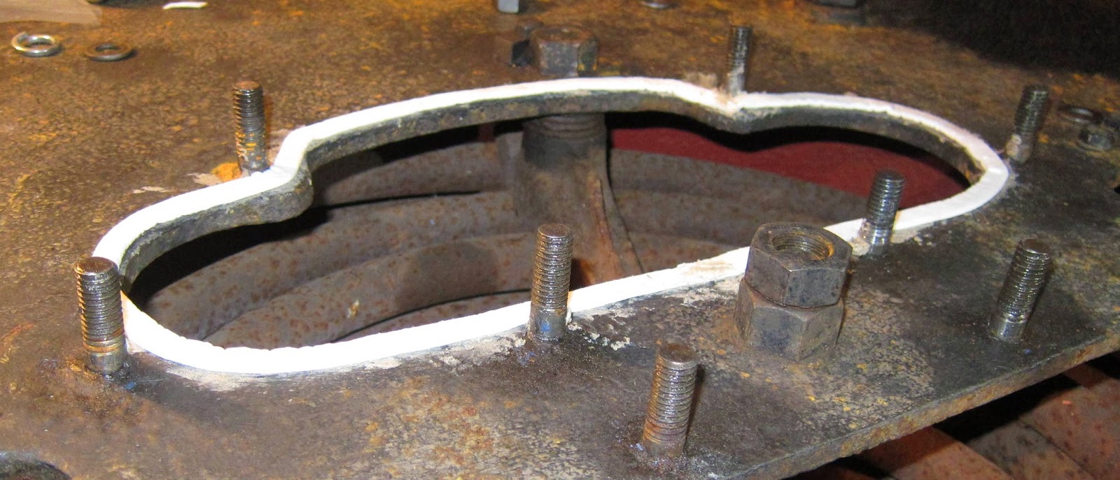
Ceramic 'felt' seal around the chimney base
Then the casting could be lowered into place without risk of displacing the tape. It was feasible to put the tape right on the edge of the top plate's hole as the hole in the casting coincided well.
Casting fully seated (1)
Casting fully seated (2)
The tape protrudes slightly on the side nearer the centre line but this will not be a problem.

It's worth noting a previous article about the sinking centre section of the boiler top plate. Before putting the castings in place, I slackened the nuts which hold the strut supporting the superheater's baffle plate. This left the top plate so that it would be flattened when the castings were tightened down and indeed this was the case. The baffle plate can then be tightened up.

The second casting was handled in the same way as the first and went in without needing to grind away space for the other superheater nut.
Both castings in place
RHS Bifurcating exhaust pipe fitted
View down through to the superheater showing the blast nozzles
(My boots were clean at the start of the day!)
The bifurcating exhaust pipe to the right is still to be fitted. Then there are the four tubes and outer heat shields to fit. A new cover will be needed to keep the rain out as the chimneys will protrude out through the cab roof.

Tuesday, 23 December 2014

Keeping the Heat In (A Cover-Up!) (1)

From the beginning, Sentinel 7109's boiler had a top cover as shown in this old photo below:
Inside cab (a long time ago)
(Photographer unknown. If you claim to own this photo, please leave me a comment).
The cover was part of the miscellaneous collection of items belonging to but not fitted to 7109 on arrival at Midsomer Norton in 2004.

It has lain largely untouched for the last ten years but its turn has finally arrived. Looking at its original condition, it's not difficult to imagine why I'd ignored it until now.
Original condition showing the rusty edges
It doesn't look much better in the old photo at the top.
Close up of top/side join
The cover was made with top and side panels riveted to a curved angle iron support piece. As a guess, I would say that the riveting prevented any rust-proofing from getting between the angle iron and top or side panels. Thus continued exposure to condensation and wet caused rust to form and squeeze apart the joints. The result was a 'corrugated' appearance and many sharp edges. I could not see how this could be simply 'tarted up' without complete disassembly.
No better from the inside
I ground off all the 150 or so rivets for the various joints and punched them out. (The idea of removing 150 rivets was the main reason why I had kept well away from this task before! I even had to replace my long-serving angle grinder after it started to issue metal gear fragments and smell of hot plastic!). Eventually I was then able to practise my panel beating technique to flatten the areas to be re-joined.
Half top cover after deconstruction
The temporary joins look a lot worse than they really are. They will be screwed together with dome-head screws which bear a resemblance to rounded rivet heads.
Close up, better than it was
Now, after a coat of red oxide paint, one of the top covers is starting to look presentable.
After a coat of red oxide primer
Potentially, the cover could get very hot as it sits on top of the firebox and superheater which at times can glow red with heat. Much of the space will need to be filled with ceramic wool wadding to keep the heat in.

Also worth noting is some detail in the old photo at the top of the article. The superheater tubes coming out from the top of the boiler to the regulator and stop valve assembly are lagged. I think we had better do that too (could be a little hot to the touch otherwise!).

Sunday, 30 November 2014

No Longer a Screw (too) Tight!

Sentinel 7109's new chimney castings, having been machined to have flat bases, need a nice flat boiler top surface to sit on. Sounds simple enough except that lately I'd begun to wonder about the actual flatness of the boiler top plate on which the castings would come to reside. So one day I took along a straight edge and looked a bit more closely.
A Sinking Feeling
It was clear from the straight edge that all was not quite as I'd hoped and that there was probably 1/4" sag in the centre at the point where the superheater was supported.

Even more closely:
Another Sinking Feeling
And the other way:
And Yet Another
As the lowest point seemed to be where the superheater's support was located, I surmised that perhaps the superheater might have been tightened down so much that it was distorting the top plate.

Whether it would be possible for the top plate to be flattened simply by screwing both chimney bases down tightly, I did not want to entertain in case a casting cracked in the process.

I then checked the effect of loosening the superheater support (where the two nuts are). Indeed the sinking could be lessened to 1/8" instead of a 1/4" which I felt would be satisfactory.

It's clear that it will be better to slacken the superheater support and tighten down the chimney castings first to make the top plate flat. Then tighten the superheater with the chimneys in place.

Nice idea but see the picture below:
Space between the old chimney bases
The new castings leave even less space between them than the old castings shown above so it will not be easy to wield a spanner in there.

But where there's a will...
Related Posts Plugin for WordPress, Blogger...