Thursday 28 March 2013

A Nice (Replacement) Pair!

Those of you who have been following the 'blog for a while will know that the restoration started out with a number of original bits missing. One by one, I've been acquiring or making replacements, sometimes authentic to the originals but not always. One example of the latter is the safety valves.

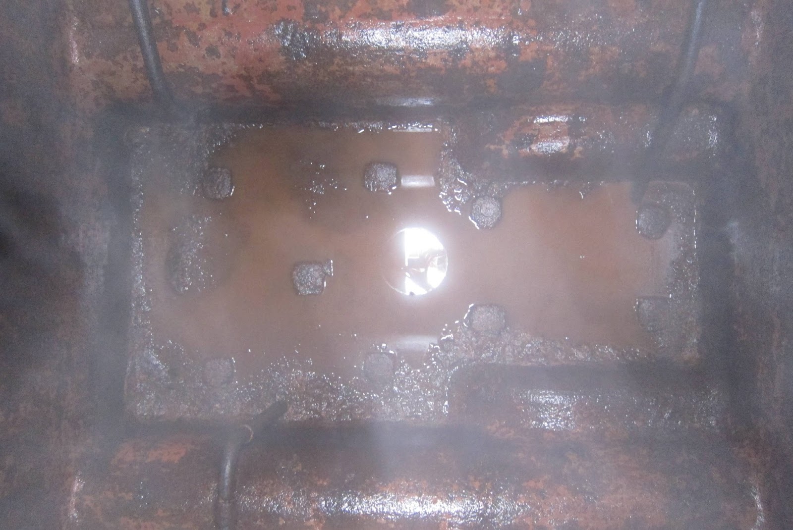
A typical Sentinel safety valve assembly is shown in the picture below which belongs to Isebrook at Quainton Road. It is very much an integrated assembly with the lower casting having the valve seats. Unless all the parts are present, this is not going to be an easy reconstruction - particularly as it needs to be accurately calibrated for the release pressure.
Isebrook's (6515) Safety Valves
Long ago, I concluded that this approach belonged in the 'too difficult pile' and that modern items should be used instead. (Later, if suitable authentic items become available, who knows what may happen but at least I know that the safety system will be reliable and accurately calibrated).

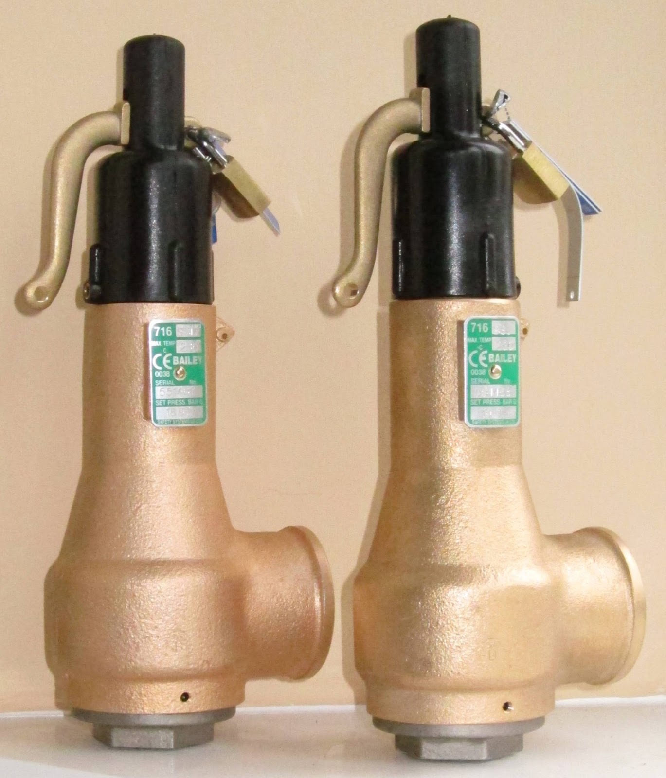
So these are the new devices: Bailey Birkett type 716SSL, size DN20 with the inlet below (3/4" BSP) and outlet to the side (1 1/4" BSP). One is set at 275 psi (18.97 bar) and the other at 280 psi (19.31 bar). The SSL part of the type indicates that the valve seats are made of stainless steel to handle the elevated boiling point found at 275 psi. Many thanks to South West Engineering Supplies of Chippenham for obtaining these.
Joyce's (7109) Brand New Safety Valves (1)
Each has the capacity to release the entire boiler steam output alone (4600 lbs/hours or 2087 kgs/hour).
Joyce's (7109) Brand New Safety Valves (2)
Now for the plumbing! Again, as the pressure is 275 psi, malleable iron pipe fittings are just able to withstand the working pressure but without a good enough safety margin. As a result, mild steel fittings and pipe work will be used.


Monday 25 March 2013

Pipe Down

I've begun to refit the steam feed piping to the engines from the boiler starting at the front end (because there is a section that will need to be remade but can't be done until the rest is in place).

This 'underneath' photo shows the steam pipe in white which runs down the centre of the loco under the water tank.
Curved white steam pipe descending from the engines above
The straight section of the pipe extending beyond the axle was unsupported on arrival in 2004 but there are fixings for support brackets on the bottom of the water tank (the grey thing in the centre of the photo).

Progress today was to attach the small bore pipes from the engines to a 'Y' piece which connects to the wider bore steam feed pipe.
Rear engine viewed from right hand side
View from left hand side, front engine on the left
The pipe from above
And the next job...
... is to connect the long straight steam feed pipe. Before that can be done, the mating face at the boiler end needs to be cleaned-up to make a leak-free seal.

All these pipe joints, bar the one at the bottom of the 'Y' piece, have used annealed copper washers with graphite grease. The one at the bottom of the 'Y' kept its original joint material but with new graphite grease.

Monday 18 March 2013

Built like a Tank

I mentioned needing to de-scale Sentinel 7109's water tank in an earlier article.

The water tank is the large four-inch thick cast iron object between the cab/boiler and engines.
Central 600 gallon water tank
In 2004 just after 7109 arrived at Midsomer Norton Station, I poked my camera into the tank to see what it would be like.
Bottom of Tank in 2004 (Loco front to the right)
I used a domestic vacuum cleaner with a very long tube to lift most of the scale and rust deposits from the bottom leaving it a lot clearer but with plenty of scale still sticking to the tank walls.

After considering a colossal amount of Kilrock-K, I resolved that the simplest and cheapest way to remove the loose scale was to use a pressure washer. The results are pictured below (taken some time after the spray should have subsided).
Lots cleaner
Despite having waited for the spray to subside, the next picture shows a strange, persistent and welcome phenomenon.
Where has all that steam come from?
It really wouldn't go away.
Perhaps Joyce is starting to realise she's coming back to life and making her own contribution?

It could be a sneer at the photographer from above!
Off subject but I noticed an unexpected reflection
before the tank dried out!
Cleaning out the tank has been holding me back from fitting the water valves to the left hand side.

Sunday 10 March 2013

Boiler Fittings (6)

At the end of my last article on the boiler fittings, I was left having to think a while as to how to make the superheater actually fit its fittings.

I realised that the boiler top-plate and four superheater rings were all tightly fixed together by their mountings. As a result, I was having to cajole each ring against the wishes of the rest of the rings.

By loosening the fixings, each ring could be adjusted independently of the others and of the boiler top-plate leaving much more slack to play with.

So after some careful height adjustment with the sky-hook, here's the result.
Regulator and superheater connection (1)
Regulator and superheater connection (2)
Not obvious in these photos is the use of 2mm thick annealed copper washers to seal the mating faces of the superheater joints.
Steam feed manifold (1)
Steam feed manifold (2)
Steam feed manifold (3)
My apologies for the poorer quality of these photos, I forgot my usual Canon Powershot S95 and had to resort to a mobile phone!

If you are still wondering about the skyhook, click here!

Friday 8 March 2013

Boiler (Not) Fittings (5)

Having fitted the steam feed manifold and regulator assembly to the boiler, the next job is to join them together using the 4-ring superheater.

I recall being hugely relieved when I was told in June 2011 that our superheater was new old stock and had never been used before. Brilliant, I thought; however, there is a down side to this in that it has also never been joined to a set of steam fittings before... Could this mean that it might not fit first time 'out of the box'?

Have a look at these:
Superheater not quite above the regulator assembly
Superheater not quite above the steam feed manifold
In fact, the superheater really does not align very well at all! I decided on Monday 4th March that it was time to put this aside and think about it for a while!

Not only do the fittings not line up but when they eventually are 'persuaded' into place, the boiler top plate will then not align with the boiler top itself!

In 1973, during my student apprenticeship in Newcastle, I spent 6 weeks in a fitting shop at C A Parsons & Co Ltd, the sadly long-gone Turbine-Generator manufacturer. I never thought I'd ever find that experience useful again - little did I know what I'd need in later life!

Tuesday 5 March 2013

Sentinel Conversion Loco (and no clothes!) (4)

Mike Hart has sent some more photos about his progress restoring Gervase at Elsecar Heritage Railway.

Mike comments (28th Feb. 2013): "Today we shunted Gervase out of the shed at Great Central Railway so it could go on the pit to be weighed and have its springs adjusted. We will leave Gervase with her clothes off for ease of access and any final adjustments when we steam her up for test running. Nearly there - at last!"

These photos were taken outside Locomotive Maintenance Services at The Great Central Railway, Loughborough. Earlier photos (2), Earlier photos (1).
Front view showing vacuum brake and steam heating fittings
Off-side front
Near side showing mechanical lubricator mechanism
Compare with earlier view
Single Chain drive and gear-case
This is very different to 7109's dual chains and twin gear-cases
Off-side rear
Now how about a signal red under-belly for 7109?
Related Posts Plugin for WordPress, Blogger...