Friday 11 October 2013

Vacuum Braking (2) Design (1)

In Vacuum Braking (1) Requirements I set out the way I was thinking about approaching Sentinel 7109's vacuum braking system. Here I'll develop my initial design ideas but show that a discussion with a more experienced engineer can reduce time, money and complexity. (Many thanks to Steve Roberts, Engineer, at the Middleton Railway in Leeds).

Firstly, on looking into the symbols needed to draw a system such as this, I found that there was some diversity in websites depicting what I hoped would be a standard. Anyway, these are what I've settled on for subsequent diagrams. (Click on the diagrams to enlarge them).
Diagram Symbols' Definition
I had two ideas which I felt would satisfy requirements 1-4 in Vacuum Braking (1) Requirements. The first is fairly simple, the second more complicated and to get over a potential problem with the first.
Single large ejector
From left to right: the boiler at up to 275 psi feeds a globe valve used to isolate the system when not in use. This feeds a pressure reducing valve to take the pressure down to a level better suited to a vacuum ejector. A pressure gauge is included at this point to measure the setting of the reducing valve.

I've then shown a press-to-open whistle valve to allow steam to the ejector. The idea is that, by using a single large ejector, it can be switched-in and create a vacuum quickly only when required. Thus, a little leakage in vacuum can be overcome by a quick 'blip' on the whistle valve. (More to follow).

The ejector sends its exhaust to atmosphere - preferably via the ash-pan to help reduce clinker formation although it would be more spectacular to send it up through the cab roof!

The ejector's suction port is connected to a swing-flap check valve to maintain the vacuum when the ejector is switched off. Otherwise air could enter the system via the ejector's exhaust port.

Next comes a DMU type of brake valve. This enables the driver to connect the train pipe to the ejector to release the brakes ('Running'), to connect the train pipe to atmosphere to apply the brakes ('On') or to seal the train pipe to hold the braking vacuum at the level set ('Lap').
The brake valve feeds the train pipe where there is a limit valve to ensure that no more than 21" Hg vacuum is generated.
Finally, there is a vacuum gauge to let the driver know what his brakes are doing. They are off above about 18" Hg.

The above seems OK assuming that there is only a small amount of leakage in the train pipe. If the leakage is greater then a second smaller ejector can be added to operate continuously in parallel with the large ejector.
Additional small ejector
The small ejector follows a globe valve used to isolate or reduce the steam supply to the ejector. Another swing-flap check valve follows to enable the ejectors to operate independently.

Given ejectors of suitable capacity, the above possibilities allow the four requirements in Vacuum Braking (1) Requirements to be satisfied. 21" Hg vacuum can be produced in the time required; leakage can be overcome by occasionally 'blipping' the whistle valve; the pressure reducing valve insulates the ejector from lowered boiler pressure and the DMU valve includes the driver's brake valve settings.

All looks good until some better informed experience is added.

At the Middleton Railway, I was shown a vacuum equipped diesel shunter in operation. As a light engine, its vacuum hoses were linked back to 'dummies' to seal them when not in use. With the engine running and the vacuum pulled to 21" Hg, on stopping the engine, the vacuum level dropped to brake-on levels within about 10 seconds - and this was just the engine with no train attached!

The impact of this situation would be that, with the systems above using a whistle valve, the driver would be forever distracted by having to monitor the vacuum gauge and be 'blipping' the brake valve. I doubt if that would be popular with drivers!

The 'Lap' setting of the brake valve would really not be of any use at all. (With air braked systems, 'Lap' works better because leaks are easier to detect and the sealing is of a better, more modern type).

I was also shown a small 0-6-0 steam loco with a single Penberthy No 3 ejector which is operated continuously. To apply the train brakes, air is let into the train pipe even though the ejector is doing its best to suck the air out at the same time! The No. 3 ejector is also satisfactory at pulling the brakes off in a reasonable time on its own (with the brake valve closed, of course!).
Penberthy No 3 Ejector and reducing valve with blue cap
Steam enters via the reducing valve on the right, then through the ejector which exhausts to the ash pan on the left (to dampen the ash). The vacuum train pipe is off the side of the ejector via the elbow pipe joint and to the right.
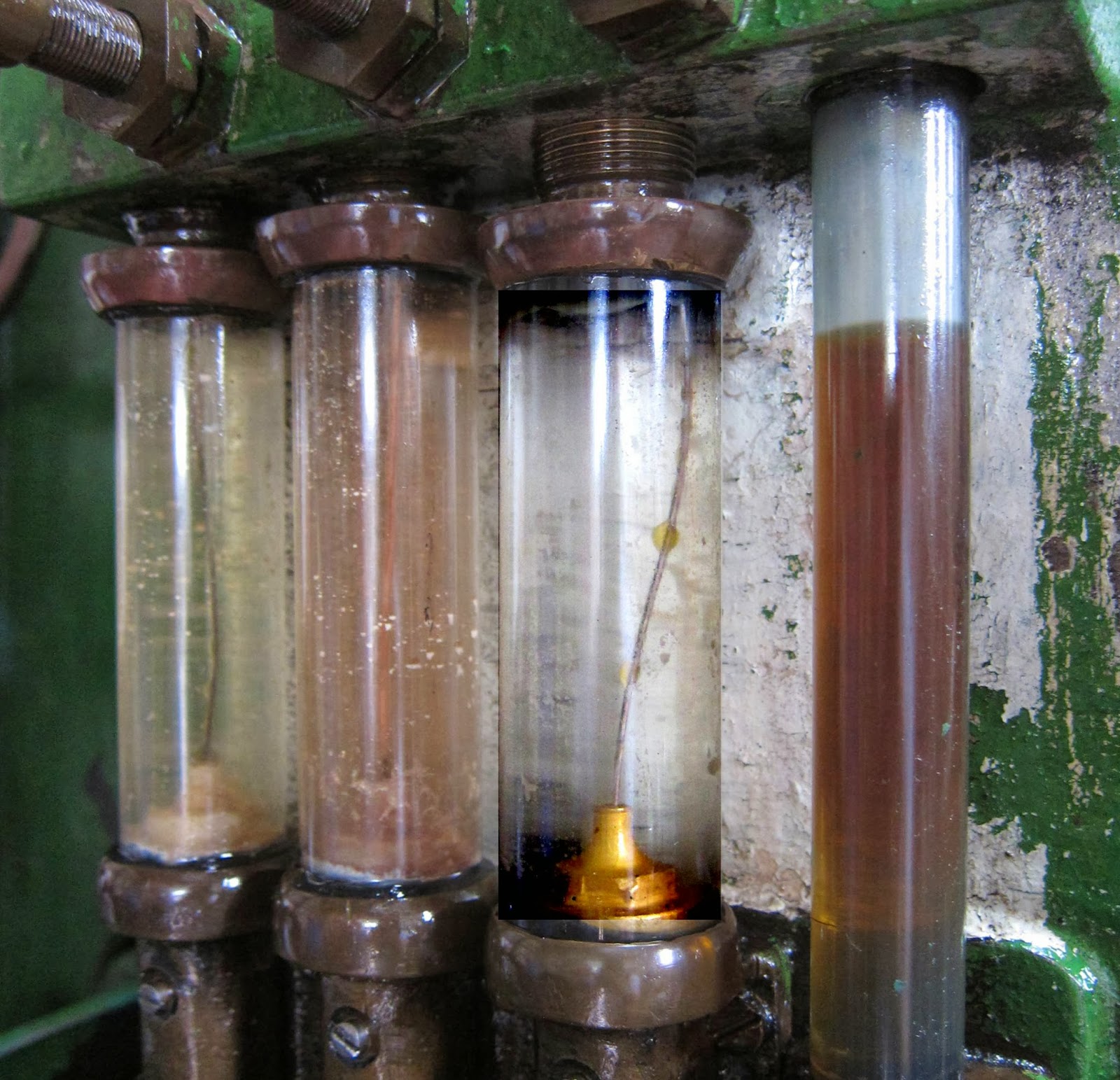
Vacuum pipe and steam supply
This system is shown in the following diagram (with an added steam pressure gauge).
Middleton Railway influenced Vacuum System
My concern with this simpler idea is the continuous use of steam when in operation. Instinctively, it seems wasteful; however, it may not be the case.

A 1.25" Tyco Penberthy GL type ejector operating at 60 psi uses 135 lbs/hour of steam. Sentinel 7109's boiler is capable of 4600 lbs/hour so the ejector will be using 2.9% of the boiler's maximum output - Not a lot! (Click here for reference information to these figures).

But does this still satisfy the original four requirements?

1. and 2. will be OK given the right choice of ejector.

3. will be unchanged and is a function of the pressure reducing valve.

4. can be dispensed with now that it is clear that considerably more leakage is involved than was originally envisaged. 'Lap' won't hold the vacuum level except with exceptionally well maintained rolling stock - an unlikely luxury to have!

So it looks as if things can be done more simply - time to do some more thinking!

Sunday 6 October 2013

Vacuum Braking (1) Requirements


Ejector Construction (from Penberthy literature)
Background

As an industrial shunter, Sentinel 7109 never had train braking equipment fitted. However, at Midsomer Norton (MSN), 7109 will be towing passenger trains on occasions and on pretty steep gradients. If I recall correctly, through train braking has been a legal requirement for passenger carrying since the 1870s so it would severely curtail 7109's capabilities if it was omitted!

Heritage passenger rolling stock generally has vacuum rather than air braking and, at MSN, vacuum has been chosen to be the norm. As such, some time ago I committed myself to the Research & Development needed to satisfy this requirement - little did I know what I was getting into!

I'm not going to dwell on how vacuum train braking systems work; it's covered in many places on the internet such as here.

What isn't generally covered is the requirements and design of the locomotive equipment which is what I've been figuring out for the last few weeks (if you were wondering why I haven't published so much 'blog material lately!).

Requirements - what does it have to do?

1. It shall be able to evacuate four Mk1 carriages' braking systems to 21" Hg in 30 seconds.

2. It shall be able to maintain a vacuum level in a leaky system.

3. It shall be able to raise 21" Hg vacuum level at any boiler pressure above 100psi.

4. It shall be able to:
    a. Release the train brakes (Running).
    b. Apply the train brakes (On).
    c. Hold the train brake vacuum level (Lap).

Implications of the requirements

1. 30 seconds is a reasonable time to be able to evacuate a train and pull its brakes off. This is a figure for when there is no remaining vacuum in the carriages. After a brake application, part of the system is still evacuated so the time will be shorter.

21" Hg is the gauge vacuum level for the system.

A Mk1 carriage has a vacuum system volume of about 4 cu ft. Therefore four carriages have about 16 cu ft to be evacuated in 30 seconds. Fewer carriages take less than 30 seconds!

2. Vacuum brake train pipes tend to leak so that, having developed a vacuum level, the level will often reduce allowing the brakes to come on unintentionally (it's a fail safe system). Thus a means of continually sucking a vacuum is helpful.

GWR locos use a piston vacuum pump which can be heard giving a 'Phut' for each rotation of the driving wheels. Other locos use a large ejector to get the brakes off quickly and a smaller ejector to maintain the vacuum.

It is also feasible to use only a single large ejector to take the brakes off and to maintain the vacuum by only activating it when needed. Being large, it does not have to be used for long periods so it will react fast but won't consume any steam when it is inactive. This is the solution I am minded to use but with the possibility of adding a smaller ejector in parallel if the single ejector isn't satisfactory.

3. If boiler pressure is falling, the last thing wanted is for the brakes to also start to coming on. Thus, it is wise to design the ejector system to operate at a controlled lower pressure, e.g. 80-100 psi. The boiler pressure can then fall to around 80-100 psi before the brakes are affected.

4. These functions are provided by a brake valve having 'Running', 'Lap' and 'On' settings. The ejector system will only be linked to the train pipe when in the released position.

Design Investigation

I began by contacting others in the Sentinel loco community who had worked on similar systems. To create the vacuum, it seemed that all had used Penberthy water lifting ejectors of various sizes and with a greater or lesser success. The amount of design information on these did not seem sufficient to make informed design decisions. In one case, the realisation that the ejectors were designed for water lifting had led to an internal redesign of the nozzle geometry - with some improvement. (See the diagram above for the general shape of an ejector).

Using the internet, I searched for Penberthy and found that they are an American company very much in business supporting other vacuum applications such as vacuum packaging and process industries. 'Ejector' now seems to be re-branded under the name 'Jet Pump' for possibly obvious reasons.

Jet Pumps come in a number of varieties and capacities. For 7109's purposes, it needs to be a steam pumping gas (air) type as opposed to liquid pumping of liquids, solids or gases - they're clever little devices (and some not so little)! I found a very useful application guide to Jet Pumps here.

It would seem that either a type GH or GL will be suitable.

More (lots) to follow.

Tuesday 1 October 2013

Illustrating an Old Mystery

About two years ago, a mystery was solved for me by Colin Evans regarding the inclusion of a piece of wire in the barrels of Sentinel 7109's mechanical lubricator pumps.

On 22nd September 2013, I visited the Kew Bridge Steam Museum in London. On one of the big diesel engines, with a mechanical lubricator similar to 7109's, was an excellent example of what I'd been trying to describe two years ago - an oil droplet travelling up the wire.

Have a look at the third tube from the left:
Oil droplet on the wire in the third tube from left
So this simple idea clearly seems to work!
Related Posts Plugin for WordPress, Blogger...