Tuesday 24 December 2013

Pipe Dream Come True

Back in April 2013, in a previous article, I wrote about the curved main steam pipe which was to be remade by Mendip Steam Restorations. It was to replace the original one which had been badly damaged by corrosion and pitting of the outer surface.
Original Main Steam Pipe
The replacement finally arrived on Monday 25th November 2013. It had been delivered earlier but found to not quite fit correctly. In the days when 7109 was constructed, there was not such a thing as flexible pipe. As such, the ends to which the curved steam pipe has to fit are fixed in space very precisely; hence the difficulty with making the item. However, on the brighter side, by igniting the first fire in 7109 for many decades, an oxy-propane torch was able to provide the heat to shape the pipe to fit.

Unfortunately, this was not the end of the story. Being a main steam pipe wrapping around the boiler in the cab, it's very close to the driver. Hence it's not a nice thing to have fail at an inappropriate time!

Problems were found with the end fittings such that they could not be examined by X-ray to check the soundness of the welded end flanges. Complete new ends were machined from solid to avoid the necessity for any weld at the mating faces. The new section then had to be welded to the rest of the pipe to a high standard.
Brand-New Main Steam Pipe
It looks in shape very like the old one - which is lucky really!

The original fittings have been salvaged for the new pipe.
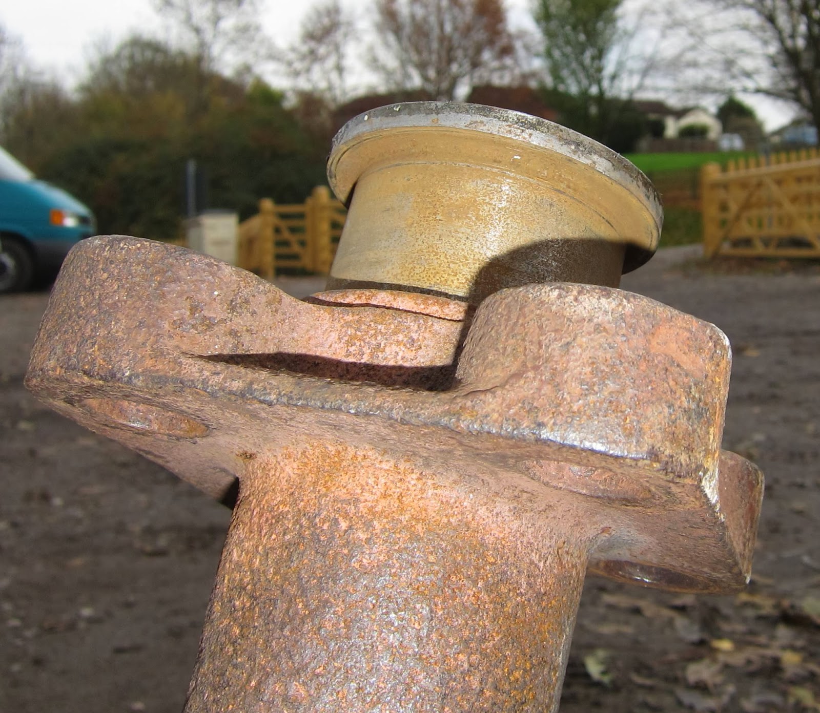
End section and flange machined from solid
Sections have been welded to pressure vessel standards.
One of the very tidy coded welds
My apologies for such a long time since the last blog article - the reason being that I have recently been heavily entrenched in the arrangements and running of the two December steam weekends at Midsomer Norton. We haven't had any steam for some years so it was bound to be a taxing time.
Bristol Harbour Railway's Peckett 0-6-0 'Henbury'
tucked up in Midsomer Norton's Goods' Shed
Much has still been going on behind the scenes with 7109 and I've now received the vacuum brake ejector from the USA (ironically stamped with the word 'China'!). More of that to follow.

Wishing you Seasons' Greetings for Christmas and the new year. 7109 didn't quite steam in 2013 but I have high hopes for 2014.


Thursday 7 November 2013

Vacuum Braking (4) Design (3)

Having settled on the GL-1 Jet Pump ejector running at 60 psi in Vacuum Braking (3) Design (2), here are the next three challenges:

1. How to connect the Ejector's American NPT threads to UK BSP threads?

2. Selecting a Pressure Reducing Valve to take the 275 psi boiler pressure down to 60 psi for the ejector.

3. Selecting a Vacuum Relief Valve for making sure that the Jet Pump does not draw more than 21" Hg of vacuum.


1. The GL-1 Jet Pump Ejector has a 3/4" steam inlet pipe thread and 1" exhaust and suction pipe threads. The trouble is that the American NPT and British BSP threads are not generally compatible and Sentinel 7109 uses BSP threads.

There are two challenges here: the pipe threads themselves and the need to be able to assemble and disassemble the ejector from the rest of the pipework. Initially, I'd started to look for simple female NPT to female BSP pipe couplings. However, it occurred to me that, if I could find a pipe fitting supplier with both NPT and BSP threaded unions, the thread linking the union halves might be the same. Thus it would be possible to create a union with NPT thread at one end and BSP at the other.
Mixed NPT-BSP Union halves
After a lot of internet searching, I eventually found Nero Pipeline Connections Ltd who seemed to have what I was looking for in stainless steel. I rang Nero and a very helpful Daryl offered to go and actually try a NPT and BSP union together. He rang back proclaiming a success with a proviso that I might have to do a little fitting to ensure a good seal between the dissimilar union halves. This was the sort of service I needed and have been able to obtain what I needed as in the photo above. Having tried the dissimilar halves together, there does not seem to be any need to persuade them to fit with each other.

2. The Pressure Reducing Valve not only has to drop the boiler pressure from 275 to 60 psi to suit the ejector but it also has to be able to let enough steam through for the ejector to do its job (and possibly a bigger ejector if ever needed).

I'd been guided towards Spirax Sarco as a suitable supplier partly because Gervase was already using one successfully but also because another Sentinel had a different type which had the persistent habit of blowing a continuous Raspberry! This was not a particularly attractive feature and one which was worth avoiding if possible (I'll diplomatically not say which Sentinel has this feature!).
Spirax Sarco BRV2S rated at 276 psi and 212 Deg C.
with Orange hat.
The beast is in the photo above. It arrived very quickly from BSS in Gloucester, UK.
Two optional features had to be chosen:
(1) To ensure sufficient steam flow was possible, I chose a 1/2" type easily capable of supporting a GL-1 ejector and even a much bigger GL-2 if found to be needed later.
(2) To be able to set the 60 psi outlet pressure, I chose an 'orange' rated spring allowing a range from 3.5 to 8.6 bar (60 psi = 4.1 bar).

The full specification of the BRV2S can be found here.

3. The Vacuum Relief Valve has to let air into the vacuum pipework when the 21" Hg level is reached. It also has to be able to let more air in than the ejector can pump out so there is a size factor too.

It took me a long time to find a supplier of a suitable device. Eventually, I found Flowstar of Kingston upon Hull, UK, who distribute products made in Hamburg, Germany, by Niezgodka GmbH. The Type 91, size 1 with a Viton seal and 3/4" male thread fitting is the chosen one.
The Niezgodka VRV data sheet has most of the detail while an additional data sheet covers the discharge capacity (2nd column under '18'). Note: 1 cu metre = 35.3 cu feet).
The size 1 type is good for 50 cu metres/hour = 29.6 cu feet/minute. (I enquired about the empty cells in the discharge capacity table and, for the size 1, 50 cu metres/hour also applies at greater vacuum levels than -0.6 bar). 29.6 cu feet/minute is plenty to overcome the suction possible from a GL-1 ejector or a GL-2 should it ever be necessary. So at least I won't have to replace all the parts should I find I need a larger ejector after all!
Niezgodka Type 91, size 1
Note: the Penberthy Technical Data Manual (page 9) shows a graph which indicates that a GL-1.5 ejector running on 60 psi is capable of 13.5 cu feet/minute at a suction pressure of 21" Hg gauge (= 9" Hg Abs.). Therefore it is safe to assume that a GL-1's capacity will be less than 13.5 because it is smaller. A GL-2 is not twice the size of a GL-1.5 so the 29.6 cu feet/minute of the VRV will be more than a GL-2 can remove.

Next, I'll look at the boiler's isolation valve, the reason why a curvaceous syphon pipe is used with a steam pressure gauge and possibly at the driver's brake valve.

Friday 1 November 2013

Vacuum Braking (3) Design (2)

Having laid down the requirements and played with some design ideas, now it's time to start making some decisions and begin the shopping.

The decision from which follows all the other design choices is the size and capacity of the Vacuum Ejector (Jet Pump).

I've decided to use a bronze Penberthy GL-1 Jet Pump operating at 60 psi and which has a vacuum pipe of 1" nominal inside diameter. (see pages 8, 9 of the link)

This is why:
Extracted from the Penberthy Jet Pump Technical Data manual, this is the sequence of activities to determine the best item for the job.
Instructions
So step 1 converts our requirement for four Mk1 carriages (16 cu ft/30 secs) into minutes/100 cu ft/min. which equates to 3 minutes/100 cu ft.

For steps 2 & 3, have a look at the table below (also extracted from the Penberthy Jet Pump Technical Data manual (click it to make it readable)):
Jet Pump Selection Chart
This next table of conversions is also needed in step 4 to determine the steam consumption (right hand column above) for Jet Pumps other than a 1.5" size.
Conversion of table figures for non-1.5" Jet Pumps
In the first table, I've highlighted the GL-1 column and the 60 psi 10" Hg Abs. row. (From the table, the GL jet pumps seem to be most efficient at around 60 psi. 10" Hg Abs. is equivalent to 20" Hg gauge which is the nearest figure to the 21" Hg gauge vacuum level to be achieved).
Two columns to the right of my highlight, is a figure of 3.7 for a GL-1.25 jet pump. Although the figure is fairly close to the 3 minutes/100 cu ft required, the GL-1.25 uses 2.9% of the boiler capacity (See Vacuum Braking (2) Design (1)). Whilst 2.9% is OK (135 lbs/hour), a GL-1 uses only 76 lbs/hour or 1.6% of boiler capacity. With these figures, it's worth having a look again at the original requirements.

(The lbs/hour figures come from the right hand column of the first table multiplied by the capacity factor for the size of jet pump in the second table. The first table is normalised for a 1.5" jet pump but converted for other sizes by the capacity factor to avoid having to produce a separate table for each jet pump size, e.g. a GL-1.5 at 60 psi working to give 10" Hg abs. vacuum uses 221 lbs/hour. A smaller GL-1 uses 0.344 x 221 = 76 lbs/hour - only 1.6% of the boiler's 4600 lbs/hour capacity).

Requirement 1 was for four Mk1 carriages, i.e. 16 cu ft of evacuation space in 30 seconds. In fact, 16 cu ft only needs to be evacuated fully when the system has been full of air. Once evacuated and the brakes applied, because the carriage vacuum cylinders are still partly evacuated, the full 16 cu ft volume does not need to be evacuated. Hence the requirement can be relaxed to some extent.

Requirement 1 assumed four Mk1 carriages. At Midsomer Norton, it is very unlikely that as many as four would be involved and two carriages or occasionally three would be nearer the mark.

Thus if two carriages are involved, a smaller GL-1 should be able to evacuate 8 cu ft in 30 seconds and reduce the steam consumption accordingly.

Arguably this is cheating; however, without an original requirement figure, it is very difficult to know what to aim for. Having gone round the calculation loop once, the implications of the requirement have now become apparent and show that there is a good pragmatic case for using a smaller Ejector - particularly if it is being run continuously.

Compared with the Penberthy No. 3 size water lifting ejector having a 1" suction pipe size, the GL-1 has the same suction pipe size but is specially designed for sucking air and not water. So, intuitively, the GL-1 is a similar size to the No. 3 type used on other Sentinels but should perform more efficiently.

Recalculating the figures for two Mk1 carriages with a GL-1 Jet Pump gives a time of around 0.5 minutes to evacuate two carriages whilst using 7.6 gallons of water per hour.

Well! That's the theory anyway.

These Penberthy Jet Pumps are imported by Jenex Ltd of Great Yarmouth, UK. I'm very grateful to Mark Collins of Jenex for helping me to order the right item.

Friday 11 October 2013

Vacuum Braking (2) Design (1)

In Vacuum Braking (1) Requirements I set out the way I was thinking about approaching Sentinel 7109's vacuum braking system. Here I'll develop my initial design ideas but show that a discussion with a more experienced engineer can reduce time, money and complexity. (Many thanks to Steve Roberts, Engineer, at the Middleton Railway in Leeds).

Firstly, on looking into the symbols needed to draw a system such as this, I found that there was some diversity in websites depicting what I hoped would be a standard. Anyway, these are what I've settled on for subsequent diagrams. (Click on the diagrams to enlarge them).
Diagram Symbols' Definition
I had two ideas which I felt would satisfy requirements 1-4 in Vacuum Braking (1) Requirements. The first is fairly simple, the second more complicated and to get over a potential problem with the first.
Single large ejector
From left to right: the boiler at up to 275 psi feeds a globe valve used to isolate the system when not in use. This feeds a pressure reducing valve to take the pressure down to a level better suited to a vacuum ejector. A pressure gauge is included at this point to measure the setting of the reducing valve.

I've then shown a press-to-open whistle valve to allow steam to the ejector. The idea is that, by using a single large ejector, it can be switched-in and create a vacuum quickly only when required. Thus, a little leakage in vacuum can be overcome by a quick 'blip' on the whistle valve. (More to follow).

The ejector sends its exhaust to atmosphere - preferably via the ash-pan to help reduce clinker formation although it would be more spectacular to send it up through the cab roof!

The ejector's suction port is connected to a swing-flap check valve to maintain the vacuum when the ejector is switched off. Otherwise air could enter the system via the ejector's exhaust port.

Next comes a DMU type of brake valve. This enables the driver to connect the train pipe to the ejector to release the brakes ('Running'), to connect the train pipe to atmosphere to apply the brakes ('On') or to seal the train pipe to hold the braking vacuum at the level set ('Lap').
The brake valve feeds the train pipe where there is a limit valve to ensure that no more than 21" Hg vacuum is generated.
Finally, there is a vacuum gauge to let the driver know what his brakes are doing. They are off above about 18" Hg.

The above seems OK assuming that there is only a small amount of leakage in the train pipe. If the leakage is greater then a second smaller ejector can be added to operate continuously in parallel with the large ejector.
Additional small ejector
The small ejector follows a globe valve used to isolate or reduce the steam supply to the ejector. Another swing-flap check valve follows to enable the ejectors to operate independently.

Given ejectors of suitable capacity, the above possibilities allow the four requirements in Vacuum Braking (1) Requirements to be satisfied. 21" Hg vacuum can be produced in the time required; leakage can be overcome by occasionally 'blipping' the whistle valve; the pressure reducing valve insulates the ejector from lowered boiler pressure and the DMU valve includes the driver's brake valve settings.

All looks good until some better informed experience is added.

At the Middleton Railway, I was shown a vacuum equipped diesel shunter in operation. As a light engine, its vacuum hoses were linked back to 'dummies' to seal them when not in use. With the engine running and the vacuum pulled to 21" Hg, on stopping the engine, the vacuum level dropped to brake-on levels within about 10 seconds - and this was just the engine with no train attached!

The impact of this situation would be that, with the systems above using a whistle valve, the driver would be forever distracted by having to monitor the vacuum gauge and be 'blipping' the brake valve. I doubt if that would be popular with drivers!

The 'Lap' setting of the brake valve would really not be of any use at all. (With air braked systems, 'Lap' works better because leaks are easier to detect and the sealing is of a better, more modern type).

I was also shown a small 0-6-0 steam loco with a single Penberthy No 3 ejector which is operated continuously. To apply the train brakes, air is let into the train pipe even though the ejector is doing its best to suck the air out at the same time! The No. 3 ejector is also satisfactory at pulling the brakes off in a reasonable time on its own (with the brake valve closed, of course!).
Penberthy No 3 Ejector and reducing valve with blue cap
Steam enters via the reducing valve on the right, then through the ejector which exhausts to the ash pan on the left (to dampen the ash). The vacuum train pipe is off the side of the ejector via the elbow pipe joint and to the right.
Vacuum pipe and steam supply
This system is shown in the following diagram (with an added steam pressure gauge).
Middleton Railway influenced Vacuum System
My concern with this simpler idea is the continuous use of steam when in operation. Instinctively, it seems wasteful; however, it may not be the case.

A 1.25" Tyco Penberthy GL type ejector operating at 60 psi uses 135 lbs/hour of steam. Sentinel 7109's boiler is capable of 4600 lbs/hour so the ejector will be using 2.9% of the boiler's maximum output - Not a lot! (Click here for reference information to these figures).

But does this still satisfy the original four requirements?

1. and 2. will be OK given the right choice of ejector.

3. will be unchanged and is a function of the pressure reducing valve.

4. can be dispensed with now that it is clear that considerably more leakage is involved than was originally envisaged. 'Lap' won't hold the vacuum level except with exceptionally well maintained rolling stock - an unlikely luxury to have!

So it looks as if things can be done more simply - time to do some more thinking!

Sunday 6 October 2013

Vacuum Braking (1) Requirements


Ejector Construction (from Penberthy literature)
Background

As an industrial shunter, Sentinel 7109 never had train braking equipment fitted. However, at Midsomer Norton (MSN), 7109 will be towing passenger trains on occasions and on pretty steep gradients. If I recall correctly, through train braking has been a legal requirement for passenger carrying since the 1870s so it would severely curtail 7109's capabilities if it was omitted!

Heritage passenger rolling stock generally has vacuum rather than air braking and, at MSN, vacuum has been chosen to be the norm. As such, some time ago I committed myself to the Research & Development needed to satisfy this requirement - little did I know what I was getting into!

I'm not going to dwell on how vacuum train braking systems work; it's covered in many places on the internet such as here.

What isn't generally covered is the requirements and design of the locomotive equipment which is what I've been figuring out for the last few weeks (if you were wondering why I haven't published so much 'blog material lately!).

Requirements - what does it have to do?

1. It shall be able to evacuate four Mk1 carriages' braking systems to 21" Hg in 30 seconds.

2. It shall be able to maintain a vacuum level in a leaky system.

3. It shall be able to raise 21" Hg vacuum level at any boiler pressure above 100psi.

4. It shall be able to:
    a. Release the train brakes (Running).
    b. Apply the train brakes (On).
    c. Hold the train brake vacuum level (Lap).

Implications of the requirements

1. 30 seconds is a reasonable time to be able to evacuate a train and pull its brakes off. This is a figure for when there is no remaining vacuum in the carriages. After a brake application, part of the system is still evacuated so the time will be shorter.

21" Hg is the gauge vacuum level for the system.

A Mk1 carriage has a vacuum system volume of about 4 cu ft. Therefore four carriages have about 16 cu ft to be evacuated in 30 seconds. Fewer carriages take less than 30 seconds!

2. Vacuum brake train pipes tend to leak so that, having developed a vacuum level, the level will often reduce allowing the brakes to come on unintentionally (it's a fail safe system). Thus a means of continually sucking a vacuum is helpful.

GWR locos use a piston vacuum pump which can be heard giving a 'Phut' for each rotation of the driving wheels. Other locos use a large ejector to get the brakes off quickly and a smaller ejector to maintain the vacuum.

It is also feasible to use only a single large ejector to take the brakes off and to maintain the vacuum by only activating it when needed. Being large, it does not have to be used for long periods so it will react fast but won't consume any steam when it is inactive. This is the solution I am minded to use but with the possibility of adding a smaller ejector in parallel if the single ejector isn't satisfactory.

3. If boiler pressure is falling, the last thing wanted is for the brakes to also start to coming on. Thus, it is wise to design the ejector system to operate at a controlled lower pressure, e.g. 80-100 psi. The boiler pressure can then fall to around 80-100 psi before the brakes are affected.

4. These functions are provided by a brake valve having 'Running', 'Lap' and 'On' settings. The ejector system will only be linked to the train pipe when in the released position.

Design Investigation

I began by contacting others in the Sentinel loco community who had worked on similar systems. To create the vacuum, it seemed that all had used Penberthy water lifting ejectors of various sizes and with a greater or lesser success. The amount of design information on these did not seem sufficient to make informed design decisions. In one case, the realisation that the ejectors were designed for water lifting had led to an internal redesign of the nozzle geometry - with some improvement. (See the diagram above for the general shape of an ejector).

Using the internet, I searched for Penberthy and found that they are an American company very much in business supporting other vacuum applications such as vacuum packaging and process industries. 'Ejector' now seems to be re-branded under the name 'Jet Pump' for possibly obvious reasons.

Jet Pumps come in a number of varieties and capacities. For 7109's purposes, it needs to be a steam pumping gas (air) type as opposed to liquid pumping of liquids, solids or gases - they're clever little devices (and some not so little)! I found a very useful application guide to Jet Pumps here.

It would seem that either a type GH or GL will be suitable.

More (lots) to follow.

Tuesday 1 October 2013

Illustrating an Old Mystery

About two years ago, a mystery was solved for me by Colin Evans regarding the inclusion of a piece of wire in the barrels of Sentinel 7109's mechanical lubricator pumps.

On 22nd September 2013, I visited the Kew Bridge Steam Museum in London. On one of the big diesel engines, with a mechanical lubricator similar to 7109's, was an excellent example of what I'd been trying to describe two years ago - an oil droplet travelling up the wire.

Have a look at the third tube from the left:
Oil droplet on the wire in the third tube from left
So this simple idea clearly seems to work!

Friday 30 August 2013

Order, Order!

As well as restoring Sentinel 7109 ("Joyce"), I've also been discovering her history. Sometimes information comes to light through a deliberate search but occasionally someone turns up a real unexpected gem.

One of these gems was kindly sent to me by John Hutchings from the Industrial Locomotive Society. There are three images which can be magnified for reading by clicking on them (and 'back-arrow' to return). They show the original works orders (7109) for the manufacture of "Joyce".
Page 1
Page 2
Not forgetting the 'sprockets'!
In amongst the information are the figures for the number of gear teeth and sprocket teeth. These allow an interesting calculation of speed per engine RPM.

Crankshaft pinion: 45 teeth.
Countershaft pinion: 102 teeth.

Axle sprockets: 27 teeth.
Countershaft sprockets: 15 teeth.

Engine speed to axle speed ratio:

102/45 x 27/15 = 4.08:1.

Wheel diameter: 36 inches.
Wheel circumference: Pi x 36 = 9.42 ft.

[Feet/mile = 5280].

MPH = (RPM/4.08 x 60) x 9.42/5280 = 13.1 at 500 RPM engine speed.

So we can expect Sentinel 7109 to be speeding along at 13.1 MPH when its engines are at 500 RPM!

Other noteworthy points in the orders show that there was an injector fitted originally and that no Weir boiler feed pump was included; it would appear to have been ordered and fitted later. The boiler was a single 'experimental' type as opposed to some earlier double-engined locos that had used two 100 HP boilers!

I'm also enquiring as to whether similar information is available for the two Radstock Sentinels.

Tuesday 20 August 2013

Camshaft Surface Finish (2)

In a May 2013 article, I was concerned about how best to remove some corrosion from the surface of one of Sentinel 7109's rear engine camshafts. Holding a file to the surface while turning the engine and camshaft using compressed air seemed a good idea at the time but it became no longer practical after the steam feed pipework had been reconnected.

So I decided, that a strip of emery paper pulled back and forth around the camshaft would have to do.

This is the before picture:
Before abrading
This is the after picture:
After abrading
And with a good slopping of crankcase oil:
Ready to go
Meanwhile, I discovered a strange phenomenon in the front engine's cam-finger chamber.
Strange glow or what?
It took me a while to figure out that the lurid green-ness was the new oil dribbling through from the cam-shift shaft oil chamber into the old oil.

Clearly visible is the word 'STEAM' stamped on the end of the camshaft. This differentiates it from the exhaust camshaft on the other side of the engine. It also looks as if there may be a manufacturing date of some time in April 1946. I had previously not been aware that the camshafts had ever been replaced.

Sunday 18 August 2013

Engines (2) Cylinders

Before looking into the cylinder tops, a brief digression. I've occasionally been asked about the four 'pips' on top of 7109's engine cowling; some enquirers had assumed these were a peculiar type of chimney where the smoke would rise from.
7109's four 'pips'
However, this is far from the case. In fact they are merely an adjunct to the cylinder covers to allow space for the top-of-cylinder automatic drain cocks. One wonders whether the 'pips' were an after-thought on the designer's part rather than a feature. Oddly enough, later designs did not have them!

Beneath each of the two covers is a pair of engine cylinders.
Rear engine's cylinders showing auto-drain cocks
When a lid is removed, inside it looks like this:...
Front engine RHS cylinder lid
... and inside the cylinder, it looks like this:
Front engine RHS cylinder
The muck is well stuck on and must have been there a long time. I've cleaned out some of it but it's hard to dislodge and will have to stay put.

The cylinder wall looks like this (the others are similar):
Front engine RHS cylinder wall
Some years ago, in my ignorance, I cleaned the cylinder walls with light machine oil. The variation in colour shows where I washed away the brown cylinder oil which probably would have been better left as it was.

On this occasion, however, I drenched the cylinder in new cylinder oil in preparation for running.
Guess who took the photo!
I did the same for all four cylinders, The piston is right at the bottom in the photo below.
Rear engine LHS cylinder
Finally, I got a bit arty and captured the picture below.
It was a fine day!
Then I put the cylinder lids back on as in the second picture from the top. Job done.

The rectangular holes in the cylinder walls are the steam inlet and outlet ports.

Saturday 17 August 2013

Engines (1) Oil Change

In a previous article, I'd begun to describe the engine oil change (but got distracted on to other oily activities!). Mid-July 2013, I did the oil change on both front and rear engines. The front engine had been topped-up with used (not too clean) crankcase oil (a rather unsuccessful attempt to fling it about by rotating the engine on compressed air. All I'd achieved was to introduce a load of sludge into the works!). The rear engine I'd drained off partly in 2009. I hate to imagine when the last oil change had taken place!
Oil filler 'cap'
Like on most internal combustion engines, there is an oil filler 'cap'. I'd read that each engine needed 10 gallons of crankcase oil so enough had been bought earlier back in 2010 (when I thought it might take less than a year to get 7109 back to life - How wrong I was!).

The crankcase oil is Hallett's Sentinel Crankcase Oil SCC680. It is a viscous oil (ISO 680) and has the specific property of enabling water to separate from it and readily sink to the bottom where there is a drain valve to let it out. This water separation property is important with a Sentinel steam engine which inevitably encounters condensation in the crankcase. (Morris Lubricants also make an equivalent crankcase oil for Sentinels).

Expecting to use 10 gallons per engine, I decided I would log the amount added against the level indicated on the dipstick.

I filled the front engine first with these results:

1 gallon: Not on dipstick.
2 gallons: 1/4 on dipstick.
3 gallons: almost 1/2 on dipstick.

I added a couple of extra litres to make it 1/2 full. (I like to mix imperial and metric units!).

Then the rear engine:

1 gallon: 1/2 on dipstick!

Oddly, I didn't expect this as none had been added since emptying.

So why did the rear engine need 1 gallon and the front 3 gallons to be half full? Simply, I don't know! However, I have to conclude that there must be something that isn't oil also in the rear engine (which was the one without the sludge added!).

Perhaps inadvisedly, I'm not going to investigate this further for now but monitor it very carefully when initial testing begins.

As yet, I also don't know whether is it is best to fill to the top of the dipstick or not. At least there is some spare oil available!

Saturday 10 August 2013

Safe Safety Valves (1)

Sentinel 7109's new safety valve system is taking shape as shown below.
The Flange and Supporting pipework
I introduced the new pair of Bailey-Birkett type 716SSL safety valves a little while back. I've now obtained the supporting steel pipe fittings and constructed the new support manifold.

Whilst on the surface this construction seems fairly straight forward, it is a safety system and therefore requires rather more formal engineering processes to ensure it is fit for purpose. (It's also my safety I'm concerned about!).

Before I retired, I spent many years on railway signalling and control centre research and development projects. Most were computer based and hence involved formal safety related system/software development project 'V' life cycles. ('V' implies: Define what it has to do; design it; implement it; test the implementation; test it meets the design; test/assess whether it does what it was defined to do originally. And don't forget the traceability!).

Safety valve pipework is somewhat more tangible than software so it would be over the top to do all that but some allusion to the principle is worthwhile.

Requirements:

Firstly, what are the requirements (i.e. WHAT does it have to do)?

The pipework shall:
1. Withstand 275psi.
2. Withstand 230DegC.
3. Support the safety valves.
4. Support the exhaust outlet pipework.
5. Allow the full output of the boiler to pass to the safety valves (4600 lbs/hour).
6. Connect to the original Sentinel boiler flange mounting.
7. Prevent condensation accumulating in the exhaust (i.e. to prevent showering nearby onlookers when the safety valves blow off!).
8. Enable easy removal of the Safety Valves for hydraulic boiler testing.

Design:

Requirements 1-8 are ultimately tested or observed; however, they all need to be taken into account during the design process.

Requirements 1 and 2 (275psi & 230DegC) are satisfied by choosing to use mild steel pipe and fittings and avoiding the weaker malleable iron which is not up to the job. It also requires that a flange to connect to the existing Sentinel flange has to conform to BS 10 (1962) Table F or better.

Requirement 3 is satisfied, firstly, by ensuring that there is a vertical 3/4" male BSP thread to connect to each safety valve and, secondly, by using sufficiently heavy gauge material.

Requirement 4 is satisfied again by using the heavy gauge material. Additional support from the cab roof may also be included later to support the exhaust pipework.

Requirement 5 is satisfied by ensuring that there are no parts of the pipework that are of a smaller diameter than the 3/4" inlet to the safety valves.

Requirement 6 is satisfied by using a compatible flange. Easy you would think but when Sentinel made their safety valve mounting, there were no standard flange sizes and ratings! So the nearest standard type needed to be chosen that involved minimal adaptation.

This resulted in a Carbon Steel flange as follows:
A screwed flange of nominal bore 1.5" (to allow a male 1.5" BSP thread to be attached).
A BS10 Table 'F' type capable of 300psi at 232.2DegC.
5.5" Diameter.
Four holes 11/16" diameter on a pcd of 4.125" to fit 5/8" studs.
0.5" thick.

The four mounting holes had to be elongated slightly to fit the Sentinel flange.

The flange dictated that 1.5" pipework had to be used which conveniently led to the considerable strength of the final structure and avoidance of any diameter less than the 3/4" inlet to the safety valves (requirement 5).

Requirement 7 is satisfied by including narrow bore draining pipes in the exhaust pipework.

Requirement 8 is satisfied by incorporating unions into the exhaust pipe elbows so that the pipe can be detached easily. The safety valves can then be unscrewed without having to take the exhaust pipework apart. A cap is screwed onto the 3/4" male thread to seal for hydraulic boiler testing.

Implementation:

Below is an early mock-up I did at South West Engineering Supplies to get the hang of the idea. It was not the first attempt; I started off using 3/4" pipe bends from the 'T' piece to the base of the valves but did not believe it was a strong enough structure to carry the weight.
Early Mock-up
The implementation evolved to the final version by using shorter 'running' nipples having no plain centre section to keep the links as short as possible and by using single piece reducers to convert from 1.5" to 3/4" diameter fittings. Thus I believe I've minimised the number of thread interfaces and maximised the strength of the structure.
The Final Version
The black 'stuff' on the threads is a jointing compound from Rocol called 'Steamseal'. It is more technically called 'Foliac Graphite and Manganese' and is specified to be able to withstand steam pressures up to 2800psi at temperatures up to 600 DegC. Good stuff! Easily exceeding requirements 1 & 2.

At this stage, requirements 1-6 have been embodied into the design and implementation.

Requirement 7's condensate draining pipe is shown below.
Condensate Draining Pipe (bottom left)
To prevent a condensate pool accumulating, the small brass fitting had to be machined so that it would not protrude into the large pipe.
Flush Drainage hole
I hope I've demonstrated how setting out the requirements before design and implementation drives towards a compliant solution. Often, it's easy to assume that what has been done before will do but that approach tends to only just get what you want if you are lucky and doesn't cater for doing something that hasn't been done before.

Of course, if you haven't got ALL the requirements identified at the start, you may still not get what you want!

Next to do is the upward exhaust pipework.

Thursday 1 August 2013

Oil Out, Rained Off, Oil In

After my last attempt to prevent oil leaking out of the front engine's cam-shift shaft oil chamber, I set out to cure the leak with a gasket of 1.5 mm rubberised cork sheeting.

The offending leak area is shown below in an old photo of the rear engine (which means I probably have a leak on that too!).
Oil Chamber Leak
First a little background: I poked my camera around underneath a Super Sentinel waggon at the 2013 Langport steam rally recently. Sentinel 7109 has very similar engines to the Super Waggon but mounted vertically instead of horizontally beneath the waggon's load platform.

I found the method of moving the camshaft to be quite different on the waggon. Chronologically, the waggon came first so Sentinel 7109's engines are an adaptation of the original approach.

The waggon used the 7109 oil chamber filler location to attach the shaft rotation lever, unlike Sentinel 7109 which has the lever on the end of the shaft.
Waggon shaft rotation technique
This is how it works: (Also on YouTube). Apologies for the background commentary!

Sentinel 7109, instead of having the waggon's rotating sleeve (which did not have to retain oil), has a clamp on sleeve, originally without a gasket.
Clamp on sleeve detached
View to the left...
...and to the right
For my second attempt at sealing the chamber, I painted a 2.75" x 11.75" rubberised cork strip with Heldite and wrapped it around the centre section, secured it in place at the top with gaffer tape and tightened the sleeve over it.

And here's what it looks like:
Attempt No. 2 with rubberised cork gasket
The proof of the pudding is in the filling with oil so that's what I did next but initially with an unexpected surprise.
Not so easy to fill; gasket a bit too effective!
Of course, I hadn't thought that the gasket would also be blocking the filler! Undeterred, I tried the hi-tech solution and jabbed it with a screwdriver.
Hi-tech solution...
...Now holding oil
About half a day later, I took this photo:
No leaks this time (after half a day)
So it looks like I've won this time round!

[Postscript: About a week later there was slight leakage - but not enough to worry about!]

Despite my early difficulties here, Sentinel obviously had faith in the method as they were still using it in post-war locos, the latest I've found it on was built in 1958 (Sentinel 9622).

In 2008, I took this picture of William's engine at Elsecar. (Sentinel 9599 built 1956).
William's Oil Chamber Sleeve
The sleeve is up from and to the right of centre. And guess what? It leaks too (unlike the modified 7109 version, attempt 2)!
Related Posts Plugin for WordPress, Blogger...