Tuesday 23 December 2014

Keeping the Heat In (A Cover-Up!) (1)

From the beginning, Sentinel 7109's boiler had a top cover as shown in this old photo below:
Inside cab (a long time ago)
(Photographer unknown. If you claim to own this photo, please leave me a comment).
The cover was part of the miscellaneous collection of items belonging to but not fitted to 7109 on arrival at Midsomer Norton in 2004.

It has lain largely untouched for the last ten years but its turn has finally arrived. Looking at its original condition, it's not difficult to imagine why I'd ignored it until now.
Original condition showing the rusty edges
It doesn't look much better in the old photo at the top.
Close up of top/side join
The cover was made with top and side panels riveted to a curved angle iron support piece. As a guess, I would say that the riveting prevented any rust-proofing from getting between the angle iron and top or side panels. Thus continued exposure to condensation and wet caused rust to form and squeeze apart the joints. The result was a 'corrugated' appearance and many sharp edges. I could not see how this could be simply 'tarted up' without complete disassembly.
No better from the inside
I ground off all the 150 or so rivets for the various joints and punched them out. (The idea of removing 150 rivets was the main reason why I had kept well away from this task before! I even had to replace my long-serving angle grinder after it started to issue metal gear fragments and smell of hot plastic!). Eventually I was then able to practise my panel beating technique to flatten the areas to be re-joined.
Half top cover after deconstruction
The temporary joins look a lot worse than they really are. They will be screwed together with dome-head screws which bear a resemblance to rounded rivet heads.
Close up, better than it was
Now, after a coat of red oxide paint, one of the top covers is starting to look presentable.
After a coat of red oxide primer
Potentially, the cover could get very hot as it sits on top of the firebox and superheater which at times can glow red with heat. Much of the space will need to be filled with ceramic wool wadding to keep the heat in.

Also worth noting is some detail in the old photo at the top of the article. The superheater tubes coming out from the top of the boiler to the regulator and stop valve assembly are lagged. I think we had better do that too (could be a little hot to the touch otherwise!).

Tuesday 2 December 2014

Leaky Axle Box Gasket

Each of Sentinel 7109's axle boxes supports its corner of the loco on a plain bearing and has an oil bath in the bottom. A large sprung pad sits in the oil bath and is spring loaded against the lower surface of the axle bearing. The pad acts as a wick to lift the oil to the lower bearing surface. As the axle rotates, oil is carried round from the pad to the weight carrying upper surface.

Some time ago, I'd noticed that one of the axle boxes seemed to be retaining its oil level much better than the other three.

I checked whether there was any water under the oil in the offending box using an oversized horse-syringe (for want of a better name).
One of these
There was a lot of water!

On removing the covers from the two right hand side axle boxes, the oil retaining one showed signs that its gasket was split at the top. On further inspection, both the right hand side gaskets were in poor condition and weren't helped by being disturbed.

New gaskets were made for both of them. (As no problem has been apparent with the LHS boxes, they have been left alone).
Front RHS gasket of 1.5mm Rubberised Cork
With the cover on, the axle boxes look like this.
Assembled (complete with missing stud!)
The missing stud will be replaced, of course (and the wheels will be painted).

Note: These photos have been cropped. If there are any modellers wishing to copy the axle box detail, leave me a comment below. I have other photos with more detail that I can supply on request.


Sunday 30 November 2014

No Longer a Screw (too) Tight!

Sentinel 7109's new chimney castings, having been machined to have flat bases, need a nice flat boiler top surface to sit on. Sounds simple enough except that lately I'd begun to wonder about the actual flatness of the boiler top plate on which the castings would come to reside. So one day I took along a straight edge and looked a bit more closely.
A Sinking Feeling
It was clear from the straight edge that all was not quite as I'd hoped and that there was probably 1/4" sag in the centre at the point where the superheater was supported.

Even more closely:
Another Sinking Feeling
And the other way:
And Yet Another
As the lowest point seemed to be where the superheater's support was located, I surmised that perhaps the superheater might have been tightened down so much that it was distorting the top plate.

Whether it would be possible for the top plate to be flattened simply by screwing both chimney bases down tightly, I did not want to entertain in case a casting cracked in the process.

I then checked the effect of loosening the superheater support (where the two nuts are). Indeed the sinking could be lessened to 1/8" instead of a 1/4" which I felt would be satisfactory.

It's clear that it will be better to slacken the superheater support and tighten down the chimney castings first to make the top plate flat. Then tighten the superheater with the chimneys in place.

Nice idea but see the picture below:
Space between the old chimney bases
The new castings leave even less space between them than the old castings shown above so it will not be easy to wield a spanner in there.

But where there's a will...

Tuesday 25 November 2014

No Longer a Screw Loose!

I confess, this is not going to be one of the most engrossing articles on Sentinel 7109 but a very short piece to record which one of the chimney castings' fixing studs needed to be welded in place to the boiler top plate. It was the one in the photo below.
The regulator is at the top right.
So, when looking to the front from the rear of the cab, the stud is the rearmost outside left hand one...
...the hidden one at the bottom left near the spanners!
A few years ago, when the top plate was refurbished and the fixing holes rethreaded, this stud was so loose, it was more likely to pull itself out than hold down a chimney. Hence the reason for the welding.

Now, just to show off a little, even I felt I'd surpassed myself with the tidiness of the weld itself. No angle grinding was used at all to cover mistakes.

Since it was always going to be a very small weld, I judged that using a stick weld would add far too much metal and need grinding away afterwards to tidy it up leaving iron filings all over the place to rust. It would also be very difficult to wield the stick in such a confined space above the boiler. So I decided to use a TIG torch.

It was still not an easy task as, not only did I have to get the welder in the cab but an Argon gas bottle as well. There really is very little space in this cab!

It was a good decision, however, as the top photo shows.

Sunday 5 October 2014

Exhausting Pipes (3)

In 'Exhausting Pipes (2)', I'd just received Sentinel 7109's machined chimney castings from Mendip Steam Restoration Ltd. with 'Interesting Times Ahead'!

I first had to fit the original pipes to the top of the new castings - the key point being that the outer shells' mounting holes also had to line up with the corresponding holes in the pipes. The pipes also had to end up being the same height as the originals.

Luck was on my side. Until this moment, I hadn't realised that the pipes were bored out at the lower end so that there was a lip to support the pipes at the correct height (assuming the new castings were the same height as the originals - which they were!).
Supporting lip at lower end of pipe
I could thus put the pipes in place over the castings (with a lot of assistance from a rubber mallet!).
Pipes on casting (ignore the bolt heads)
Outer shell mounting holes are highlighted
Then, using a couple of metal rods, I was able to support the outer shell in place and adjust the pipe orientation to suit.
Pipes line up with outer shell fixing holes
I marked out the fixing holes in the castings using the holes in the pipes, then drilled and tapped them (M10).
Tapping the castings
That sorted out the pipes but the outer shells were not in very good condition.
Corrosion around an outer shell upper fixing hole
Corrosion around outer shell lower fixing holes
I decided to attach sheets of metal over the corroded sections and weld, bolt or rivet them in place.
Outer shell upper fixing hole repaired
Outer shell lower fixing holes repaired
The sheet metal was 0.8mm thick and thus fairly pliable. To make it follow the curve of the original was a challenge but after a bit of thought I found a ratchet strap could pull it into shape so that I could drill the fixing holes.
Before...
...After(1)
After(2)
So finally, putting it all together, it looks like this (both of them similar). The M10 fixings are all stainless steel for greater resilience in this environment.
Finished (nearly)
Next, there is some fine welding to tidy up a few rough edges and a decent coat of suitable paint. Oh, and hoisting them into place (not trivial!).

Thursday 11 September 2014

Exhausting Pipes (2)

After some time in the making, the machined new chimney bases have arrived from Mendip Steam Restoration Ltd. It's worth a look back at an earlier article for where these fit atop the boiler.
New Chimney bases, Blast Nozzles & Exhaust Pipes
The photo above shows clearly how the exhaust steam flow divides into two to feed the pairs of blast nozzles.
Four Blast Nozzles showing blower rings
The short pipes showing against the orange pipes are the inlets for the blowers. More details are in this earlier article. Also try the label 'Chimneys' for all the relevant details on the subject.

The main difference between the old and new castings is the weight and hence strength. I used to be able to lift the old ones with difficulty; the new ones required help from a neighbour to get them out of my car! They are simply massive in construction and should last a very long time.

The trouble is that they will be very difficult to fit in place because of the weight! They also need the long chimney tubes to be fitted. Interesting times ahead!

Wednesday 23 July 2014

In Search of the lost Nutty

'Nutty' is one of a peculiar breed of specialised locomotives that Sentinel made in the 1920s for brickworks use. Their prime requirement was to be very squat in height; very, very squat (5'2" in fact)!
Nutty lookalike - Works number 7243 built in 1928
(Photo from Sentinel Drivers' Club collection)
Built as works number 7701 in 1929 to a 2' 11" gauge, Nutty was one of about five constructed using steam waggon components.

In order to reduce the height as much as possible, the engine was mounted horizontally and the boiler very near to the ground. It also made driving a remarkably intimate experience!
No room for foot-plate passengers!
(Photo from SDC collection)
Neither of the above photos are actually Nutty; however, the next one certainly is.
Nutty in August 1971 at the Welshpool & Llanfair Light Railway
(Photo SDC collection)
The inner workings are clearly visible if you click to enlarge the picture.

I became aware of Nutty through conversations with curators of the Narrow Gauge Railway Museum in Tywyn, Gwynedd, at the terminus of the Talyllyn Railway (where I can be found volunteering on occasions). Nutty is actually owned by the NGRM but it never seems to be found anywhere near the museum!

Although originally built to a gauge of 2'11", it was re-gauged to 2'6" some years ago and it ran on the Welshpool and Llanfair Light Railway for a while. Since that time, I do not know exactly where it has been but I'm led to believe it has spent time at Railworld in Peterborough. In 2012, it made its way to the Leyton Buzzard Railway where it is on display at the Stonehenge Works station.

I visited the LBR on Wednesday 16th July 2014 and was made very welcome indeed. I wanted to poke my digital camera into Nutty's various nooks and crannies to assess its general state. I now have around 170 photos, not all are included here!
Nutty under cover at Stonehenge Works
Yes, it is chain-driven!
Side-on view
Cab internals showing the boiler
'Under the bonnet' view showing the engine beneath the water tank
Engine, water tank and boiler feed pump
Bijou accommodation for the driver!
There are clearly a number of components missing and regrettably I omitted to enquire if they existed. However, it was a good day out and many queries answered as to the construction of this strange locomotive.

Now who volunteers to restore Nutty, reduce the gauge by another 3" and run it on the Talyllyn railway?


See my Reference Material page for information sources.

Sunday 22 June 2014

Nut & Bolt - Big Time! (2)

A few months ago, I described the manufacture of a new nut and bolt to operate Sentinel 7109's handbrake. Today I fitted it into place.
Linkage from nut to crank(1)
Linkage from nut to crank(2)
Some large split pins are still needed to complete the job. The largest I had are 1/4" diameter. 3/8" are needed. These things are big!
Optimism!
The brakes will have to be adjusted after the drive chains have been fitted but they do at least operate from the handle. The roller bearing under the handle seems to work satisfactorily.

Sunday 8 June 2014

New Trousers in the Making!

A couple of years ago, I held a Wrong Trousers Appeal. I have to admit that there wasn't a huge response to the appeal but there has been considerable progress since.

The problem facing Sentinel 7109's chimneys was that the original cast base units were well past their best and that to use them would have only led to a long outage soon after becoming steam-worthy again.

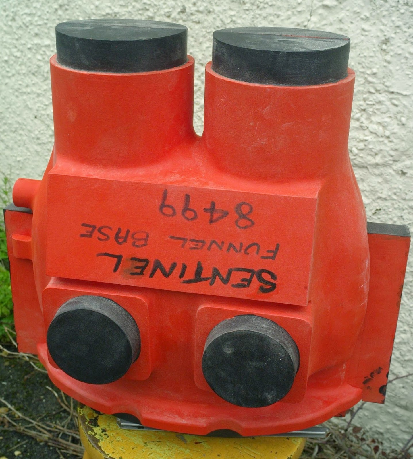
A pattern had to be made to make the mould for the castings. It was made in four parts (with possibly a fifth but I've never been able to figure out where it could fit!).
Front (1) Outside Profile
Front (2) Inside Profile
Rear (3) Outside Profile
Rear (4) Inside Profile
Sentinel, possibly due to their former ship-board equipment product range, used the term 'Funnel' rather than 'Chimney.

Six castings were eventually requested: a prototype for Sentinel 6515 'Isebrook' at Quainton Road; one each for the Sentinels at the Middleton Railway, Elsecar Heritage Railway and the Bo'Ness and Kinneil Railway and finally two for 7109.

This is the prototype used to check that the pattern was correct.
Prototype casting before machining
The new castings have an additional feature to allow extra exhaust steam to be directed up the chimneys. The feature was requested for Isebrook so that exhaust steam from the vacuum brake ejector could be used to draw the fire. The feature is not expected to be used with 7109 but will be left accessible just in case.
Prototype after machining
I took one of the original chimney units to Richard Nixon to compare the old and new. From the pictures below, it's quite obvious how much extra metal and hence strength is built into the new chimney base.
New and old comparison (1)
New and old comparison (2)
Thus I am happy that it was the right decision to go for the new casting option.

7109's castings arrived in the middle of April 2014.
Nice new pair
They are very substantial and will undoubted last a long, long time. They have been taken to Mendip Steam Restorations Ltd for machining and fabrication into complete dual chimney units.

Again, all the pipework and blast nozzles have to be carefully made to fit together. Hence, the whole job has been passed to MSR as it is beyond the capabilities of equipment available at Midsomer Norton.

Prototype and pattern pictures were kindly supplied by Richard Nixon.
Related Posts Plugin for WordPress, Blogger...